Working with TouchDRO Guide Lines
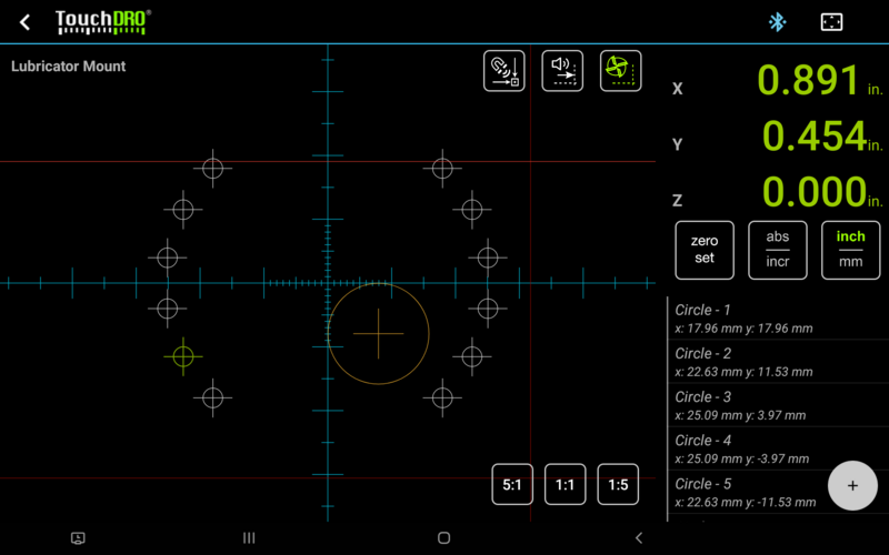
The Graphical View display has the ability to display arbitrary vertical and horizontal guides. Conceptually, guides are very similar to the single-dimensional sub-datums, with one important difference. Sub-Datums in TouchDRO use a separate coordinate system, so they can be selected and deselected without altering incremental coordinate system origins. Guides, on the other hand, directly update the incremental coordinate system origin upon activation. Deactivating a guide doesn't restore previous incremental origin for the relevant axis.

Creating Guides
There are two ways to create a guide:

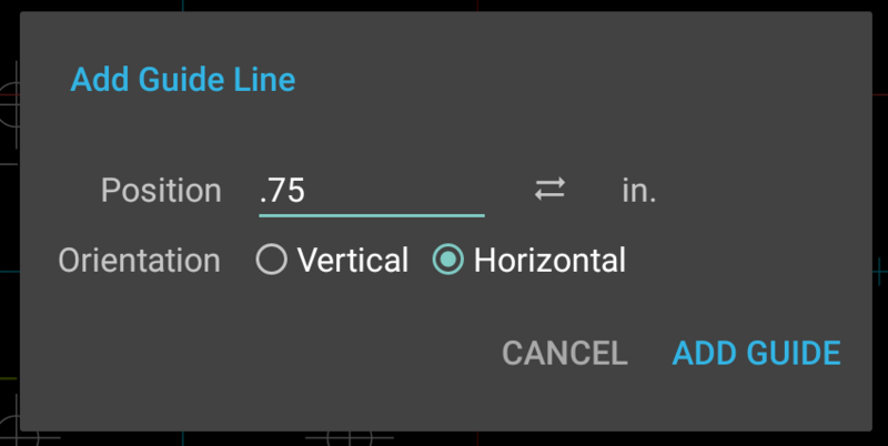
Long-pressing anywhere on the empty space in the Workspace Projection view brings up the "Create Guide" dialog as shown below. There you can select the orientation of the guide (vertical or horizontal) and position.
- Guide position is expressed in terms of a coordinate system that is selected for the given axis
- The "Position" text box is a calculator field and supports simple arithmetic equations, such as "2.05+5/64" or "--1.25". Pressing the double-arrow button next to it will copy current axis reading into the field
![Fig. 3: Add [Horizontal/Vertical] Guide Here Commands Fig. 3: Add [Horizontal/Vertical] Guide Here Commands](/assets/images/w800/manual/sub-datum-commands-add-guide.png)
Via the "Sub-Datum Commands" menu that can be accessed by long-pressing a sub-datum in the Workspace Projection view
- The "Add Horizontal/Vertical Guide Here" will add a guide that crosses the pressed sub-datum.
Deleting Guides
To delete any guide, long-press it in the Workspace Projection view and confirm the deletion in the popup dialog.
Activating & Deactivating Guides
To activate a guide, tap it in the Workspace Projection view. If another guide is active, it will be de-activated and the new guide will be activated. Visually, this is indicated by a brighter-colored line.
To deactivate a guide tap it again and it will return to the inactive state.
Modal Functions
Guides are used with two modal functions.
Automatic Proximity Warning
This mode is toggled by the Automatic Proximity Warning button that is located in the upper-right corner of the workspace projection view. When the Automatic Proximity Warning mode is active, TouchDRO will automatically turn on Proximity Warning for the relevant axis and set its target to the location of the guide. Proximity warning will be active as long as the Automatic Proximity Warning is on and a guide is selected. Deselecting a guide will turn off proximity warning for the axis.
Please note that the proximity warning will use the distance to the guide rather than the displayed zero position for the axis. As such, it's possible to use a guide in conjunction with stored sub-datums. In this case, TouchDRO will emit a proximity alarm when the spindle/cutter approaches the guide, while the display will show the distance to the active sub-datum.
Automatic Cutter Radius Compensation
This mode can be turned on and off using the Automatic Cutter Radius Compensation button that is located next to the Automatic Proximity Warning button. When Automatic Cutter Radius Compensation is on and a cutter is selected via the "Cutter Radius Compensation" function, TouchDRO will automatically recalculate the direction of the tool offset when a guide is activated. The offset will be set such that the DRO will show the position of the cutting edge that is closest to the activated guide.
Note: this function is only available when Machine Type is set to "Vertical Mill" or "Horizontal Mill" in TouchDRO application preferences.
How To Use Guides
Cutting a Slot on a Mill
Goal - cut a horizontal slot in the workpiece that is 0.75" wide using a 1/4" cutter; slot depth is irrelevant for the purposes of this example.
- Select a cutter
- Bring up the Tool Radius Compensation dialog
- Enter 0.25 into the Tool Diameter field
- Select inches (if needed)
- Set Tool Position to the center
- Press "Set Radius Compensation"
- Move the cutter to the centerline of the desired slot location
- Switch Y axis to Incremental coordinate system and zero it out
- Switch TouchDRO to Graphical View mode (if your tablet is in vertical orientation, this step is not necessary)
- Add two horizontal guides
- Long-press anywhere in the empty space of the projection view to bring up the "Add Guide Line" dialog
- Enter -0.75/2 (or -0.375) into the Position dialog, select "Horizontal" orientation and press "Add Guide"
- Bring up the "Add Guide Line" dialog again, enter 0.75/2 (or 0.375) into the Position dialog, select "Horizontal" orientation and press "Add Guide"
- Turn on the "Auto Cutter Radius Compensation" mode
- Tap the top guide and move the spindle until Y axis readout shows "0.0" position
- Make one or more cust as needed to achieve the desired depth
- Tap the bottom guide and repeat steps 7 and 8
- Remove material in the middle
Cutting a Rectangular Pocket on a Mill
Goal - cut a square pocket that measures 1.5" x 1.5"
- Select a cutter (similar to step #1 above)
- Move the cutter to the upper left corner of the desired pocket
- Switch X and Y axes to incremental mode and zero them out
- Switch to the Graphical View mode (unless your tablet is in portrait mode)
- Add two horizontal guides, one at the current position (0.0) and one at 1.5"
- Add two vertical guides, one at the current position (0.0) and one at 1.5"
- Turn on the "Auto Cutter Radius Compensation" and "Automatic Proximity Warning" modes
- Press the cutter circle to bring up the tool offset direction widget
- Click on the lower-left option (cutter to the right and bottom of the edge)
- Move X and Y axes until the readouts show 0.005". At this point the cutter will be within the perimeter of the pocket with a small buffer between it at the edge
- Activate the right vertical guide
- Plunge the endmill and take a cut towards the activated guide. When you get to within 0.1", the proximity warning will start beeping. As you keep moving, the beeps will turn to a solid sound. At that point you will be within 0.005" of the edge.
- Select the bottom guide and mill towards it. Stop when beeping switches from beeps to a solid sound.
- Repeat the above two steps for the left and then top guide.
- MIll away material in the middle.
- Repeat steps 12-14 above as many times as needed to achieve the desired depth
- Repeat steps 12-14, but this time keep moving until solid sound stops and the display reads 0.0. This will be a cleanup pass that will produce a clean sidewall.
