TouchDRO Quick Start Guide
Setting up TouchDRO is pretty straightforward, but if you are new to the system or are used to a traditional DRO, some things might be a bit confusing. The goal of this quick start guide is to outline the necessary setup and configuration steps and cover some of the basic user interface concepts and functionality.
Setup and Configuration
Before you can start using TouchDRO, you will need to install the application from the Google Play Store, configure some settings, and calibrate the scales. The steps are outlined in the DRO Build Overview.
TouchDRO doesn't come bundled and pre-configured for specific scales; so, out of the box, the application will not be configured correctly for your specific setup. This can be quickly addressed by following the Initial Configuration Guide
Finally, the system has to be calibrated, so it can correctly converd position reading from native encoder resolution to human-readable units. Calibration is covered in the DRO Scale Calibration guide
User Interface Overview
TouchDRO offers a lot of flexibility and can easily adapt to various workflows. It's designed to have a simple and clean user interface that allows quick access to the most common functionality with a single click or long-press. Most advanced (and less frequently used) functions can be accessed from various dialogs and utility pages.
The system is not constrained by a small set of physical buttons and low-fidelity LED display. As a result, many common digital readout functions are implemented differently. If you are accustomed to a traditional DRO unit, TouchDRO's user interface might be confusing at first, so let's take a quick look at some of the main concepts.
Main Screen

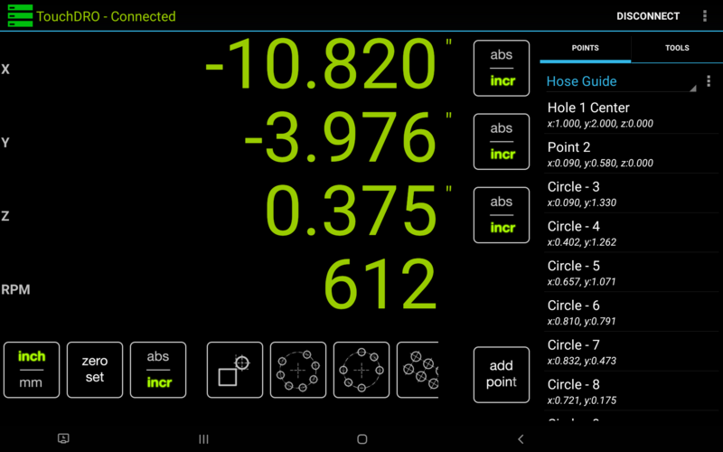
TouchDRO's main screen contains the following major elements:
- Application title bar
- Axis readouts that include the position display and a mode button
- Points/Tools panel that shows either the Saved Sub-Datums or Saved Tool Offsets
- A function strip that contains some common DRO function buttons
Application Title Bar
The title bar occupies a stip of space on the top of the screen and contains the following:
- TouchDRO application title that includes the connection status
- Connect/Disconnect button - brings up the Device Selection dialog
- Application menu button - brings up the application menu
Axis Readouts
Each axis readout consists of the position display and the "Absolute/Incremental" mode buttons. Both elements are interactive and perform a few different functions:
- Position display color indicates the DRO connection status and cutter offset:
- Gray - DRO is disconnected
- Green - DRO is connected
- Amber/Red - DRO is connected and the axis has tool offset applied to it
- In connected state, position display acts as a button that does the following:
- Short-press/tap brings up the "Axis Details" dialog
- Long-press brings up the "Preset Dimension" dialog
- Mode buttons displays the current units for the axis and performs the following functions:
- Short-pressing/tapping the mode button switches the axis between Absolute and Incremental coordinate systems
- Long-pressing the button switches the axis to Incremental coordinate system and zeroes out the reading
Function Strip
Depending on the screen size and resolution of your Android device, the function strip will appear along the bottom of the screen in horizontal orientation, or to the right of the axis readout in vertical orientation. It contains functions that apply to all relevant axes.

They include:
- "Units Toggle" function - toggles all axes between metric and imperial units
- "Set Zero" function
- Short-press/tap - switches all axes to Incremental coordinate system and sets their readings to 0. If a sub-datum is active, it is deactivated
- Long-press - sets the absolute origin for all axes to the current position (i.e. zeroes out all axes in absolute mode)
- "Mode Toggle" function - toggles between Absolute and Incremental coordinate system for all axis readout
In milling machine mode, the following additional functions appear:
- "Tool Offset" function:
- Short-press/tap - brings up the "Tool Offset" dialog
- Long-press - clears all active tool offsets
- "Hole Circle" function - brings up the "Hole Circle" dialog that can be used to create a series of equidistant holes along the circumference of a circle with the center at the current position
- "Arbitrary Hole Circle" function - brings up the "Arbitrary Hole Circle" dialog. The function is similar to the "Hole Circle", but the holes can be placed at any arbitrary spacing from each other.
- "Hole Pattern" function - brings up the "Hole Pattern" dialog that can be used to create a 2-dimensional array of holes.
In lathe mode, the following additional functions appear:
- "Tool Offset" function
- Short-press/tap - brings up the "Tool Offset" dialog
- Long-press - clears all active tool offsets
- "Radius/Diameter" function - toggles the X axis between displaying radius or diameter reading
Points Tab
Point/Saved Coordinate memory offers functionality that goes above and beyond the Saved Sub-Datum Memory of a traditional DRO unit. It is covered in more detail further down.
The panel includes the following elements:
- Workspace name dropdown:
- Displays the current workspace
- Short-press/tap allows selection of other existing workspaces
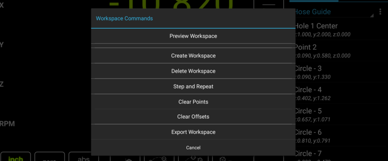
- Long-press brings up the "Workspace Commands" dialog
- Workspace Menu button ("Three Dots" button) - brings up the "Workspace Commands" dialogs

Workspace Commands Dialog - Saved coordinate list:
Tools Tab
The tab shows the list of saved tool offsets.
- Short-press/tap on a tool - brings up the "Tool Offset" dialog in milling machine mode, or applies the offset in lathe mode
- Long-press on a tool - brings up the "Tool Commands" dialog
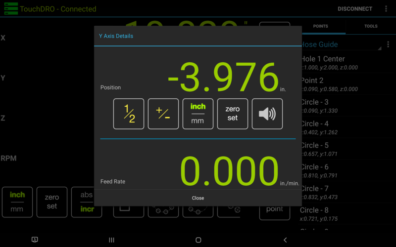
Axis Details Dialog

Axis Details dialog provides access to the following per-axis functions:
- Live position display (same as the main screen). Tapping the readout brings up the "Preset Dimension" dialog
- Live feed rate display
- Live chip load display (if the tachometer is enabled and a cutter is selected)
- "Centerline" function (the "½" button) - sets the incremental axis reading to ½ of the currently displayed value (regardless of the selected coordinate system)
- "Invert" function (the "+/-" button) - sets the incremental axis reading to the current reading with the opposite sign
- "Toggle Units" function ("Inch/mm" button) - toggles units for the axis
- "Set Zero" function:
- Short-press/tap sets incremental position for the current axis to 0
- Long-press sets the absolute origin for the current axis (after displaying a confirmation dialog)
- "Near Zero" warning function - provided audible near zero warning
Note, the "Near Zero" warning function might not work correctly on some devices. This is a known bug that has been addressed in the upcoming release of the application.
Common DRO Operations
TouchDRO is designed with the "working to zero" principle at its core. This approach requires less cognitive load during machining and is less error prone as a result. As such, most TouchDRO functions more-or-less simply provide a more convenient way to define a 0-point in various situations. This might seem too simplistic, but the combination of TouchDROs coordinate systems and datums offers a lot of power, flexibility and convenience.
Zeroing Axis Readouts
TouchDRO has several ways to set absolute and incremental zero point (origin) for all axes at once, or individually for each axis.
- To set all axes to 0 in incremental mode, tap the "zero set" button.
- To set all axes to 0 in absolute mode (i.e. set the workspace origin to the current coordinate), long-press the "zero set" button.
- To set an individual axis to 0 in incremental mode, long-press the "abs/incr" button next to it. Alternatively, bring up the "Axis Details" dialog by tapping the axis readout text and use the "abs/incr" button.
- To set an individual axis to 0 in absolute mode, long-press the "zero set" button in the "Axis Details" dialog.
Pre-Setting Axis Dimension
To preset an axis to a specific dimension, long-press the axis readout and enter the desired dimension.
Finding a Centerline
The Centerline function is called "1/2" in TouchDRO and is accessed from the Axis Details dialog. The dialog can be brought up by tapping the axis reading.
Using an Integrated Calculator
TouchDRO doesn't have a standalone Calculator function. Instead, most numeric input fields in TouchDRO accept arithmetic expressions. For example, you can enter "(1/32+7/64)*3" and the app will do the math. For more complex operations you can use the scientific calculator that comes pre-installed on the tablet.
Saved Coordinate Memory
TouchDRO comes with a robust and flexible saved coordinate memory that goes beyond the functionality of the Saved Subdatum memory of a traditional DRO unit. Therefore, it's important to keep in mind the following points:
- Due to the fact that modern tablets come with multiple Gigabytes of storage, TouchDRO can store billions of coordinates (i.e. there is no practical limit)
- Saved coordinates are organized into Workspaces.
- Coordinates are stored as a set of distances from the workspace origin. This means that you quickly move all workspace coordinates by changing the absolute origin (as outlined earlier)
- Absolute offsets are stored with the workspace, so you can have multiple setups on your milling machine and switch between them by loading the relevant workspaces.
- Activating a saved coordinate does not alter Absolute or Incremental coordinate system offsets. Instead, the sub-datum offset is applied over the top of the incremental offset. Deactivating the sub-datum restores previous incremental offset.
- In milling machine mode, Points can be saved without the Z axis coordinate. This can be handy when doing multiple operations on the same set of coordinates but with different desired Z depths
Common Operations
- To create a new Workspace, press the "Menu" icon next to the workspace name in the Point panel (three vertical dots) and select "Create Workspace". The same menu can be used to delete the workspace or clear all saved coordinates.
- To store the current position for future use, short-press the "Add Point" button. Long-pressing the button brings up the "Edit Point" dialog that will let you customize the point before saving.
- To activate/de-activate a Point, short-press it's entry in the list. Active Point will change it's display color to green.
- To edit or delete a single coordinate, long-press its entry in the list. This will bring the "Point Commands" dialog

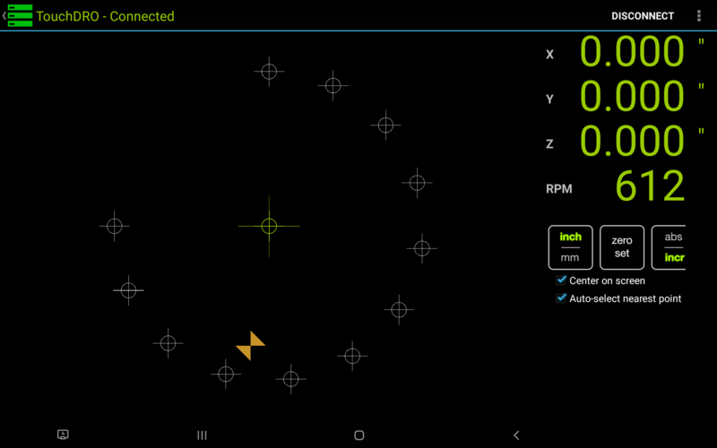
When working with a complex layout, it might be more convenient to use the "Graphical View" that can be accessed by selecting the "Preview Workspace" option from the workspace meny.

