Digital Readout Calibration
DRO scale calibration is an essential step that ensures maximum accuracy from a digital readout. In a traditional DRO, calibration is used to remove scale error. This error can be caused by two factors. First, the encoders used in the scales have manufacturing tolerances that can lead to slight deviations from nominal resolution. Second, if the scale might be mounted at a slight angle in relation to the axis of travel, resulting in a Cosine error. For instance, for each 1 degree of misalignment the encoder will have 0.0018" error over 12" of travel.
Fortunately, a linear error is very easy to eliminate by following a simple calibration procedure that uses the tools you likely already have in your shop. The process consists of moving each axis by a known distance and then telling TouchDRO what the distance was. The application will perform the necessary calculations and set the resolution accordingly.
Since TouchDRO can work with many different scale and encoder types, calibration serves an additional purpose of letting the application know what is the native resolution of each scale. Out of the box, TouchDRO internationally sets default scale resolution to 10,000 encoder pulses per Inch, which doesn't correspond to any mainstream scale resolution. Once the scales are mounted to the machine, the calibration wizard can be used to set the correct scale resolution and directions, and compensate for any linear error.
Tools and Materials
Calibration Block
You will need a stable block of known dimensions. For a small machine, a standard 1-2-3 block (or a metric equivalent) is sufficient, but a larger block would provide better accuracy since any edge indication error would be spread over a longer distance.
Dial Indicator or Edge Finder
During the calibration process, you will need to accurately indicate the edges of the calibration block. For the axes that are perpendicular to the spindle axis of rotation you can use an edge finder or even a touch probe, but for the Z axis a plunger-type dial indicator is more appropriate.
For best results, it's recommended to use a dial indicator for all axes since it can indicate the edge more accurately than an edge finder. Machine's lead screw is likely not accurate enough for this purpose; so, simply moving the axis and counting the revolution of the dial is not advisable.
Calibration Procedure
Before starting the calibration, ensure that the scales are mounted correctly to the machine and you have performed the steps outlined in the "TouchDRO Initial Configuration" guide.
Each axis input can be calibrated individually using the Calibration Wizard. The wizard can be accessed from the Axis Settings page by pressing the "Calibrate" button for the relevant input.
Please note that TouchDRO uses the conventional "Right Hand" rule for the coordinate system where the Z axis is parallel to the spindle's axis of rotation. While application will not prevent you from using a different convention, many of the functions will now work correctly.
Linear Axis Calibration
For the linear axes (X, Y, and Z) the process is as follows:
Step 1
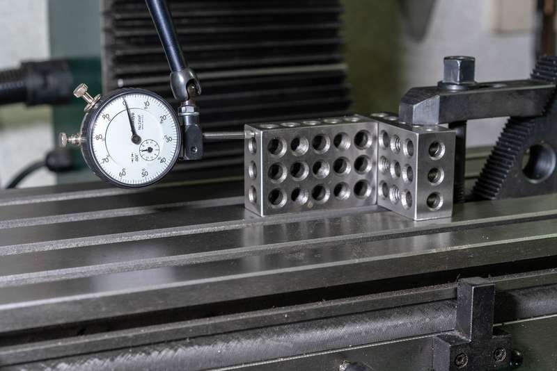
Mount the calibration block to the machine. The mounting method will vary on the machine type but the key point is to make sure that the block is held securely and the edges that you will be indicating are strictly perpendicular to the axis of travel. If using a dial indicator, you can use two 1-2-3 blocks, as shown in the photo below.
Step 2
Swipe from the left side of the screen or press the "hamburger" menu in the upper left corner of the screen to bring up the "Application Drawer"
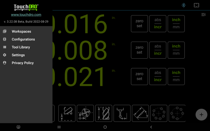
Select the "Settings" item to bring up the Application Settings screen.
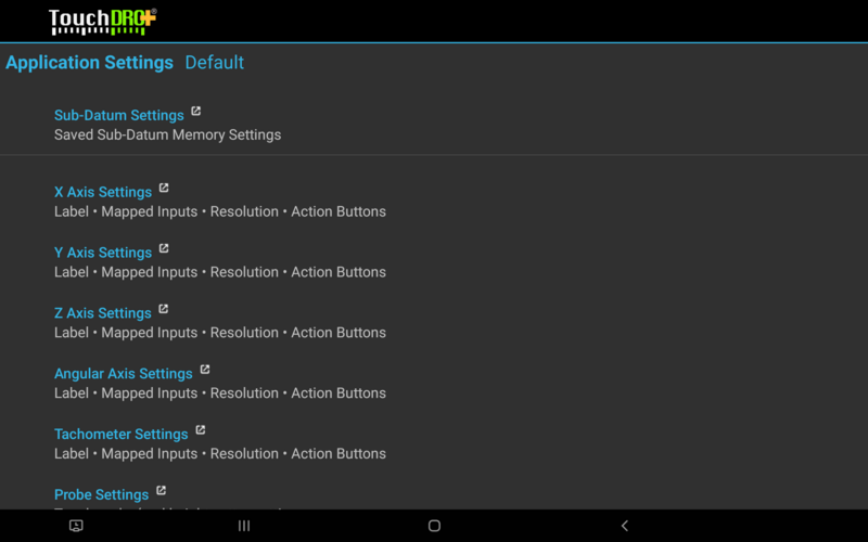
Scroll down towards the bottom of the screen; thre you will see links to configuration sections for each axis. Pressing on the link will bring up the Axis Settings Screen, where you can define which inputs should be used for the given output.
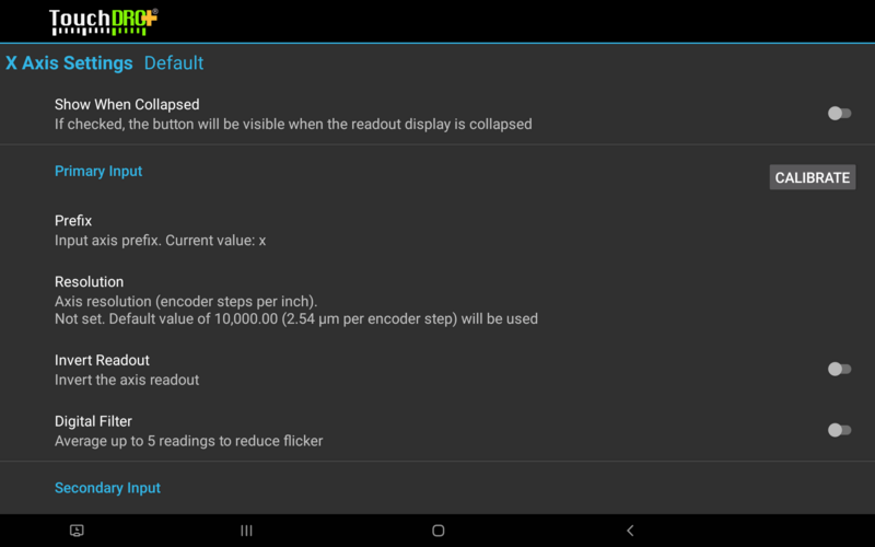
Press the "Calibrate" button next to the input you are calibrating. This will open a dialog called "Calibration Block Dimensions", asking you to enter the size of your calibration block (or the distance the axis is expected to travel). Enter the dimension of your calibration block, taking into account the diameter of the edge finder, if applicable, select the appropriate units and press "Continue"
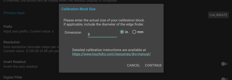
In the example shown in the photo above you would enter "3" (without quotes) and select Inches, since the X axis is measuring the long side of the 1-2-3 block. If we were using an edge finder instead of the indicator, we would enter 3.2 instead, accounting for the diameter of the edge finder.
Step 3
The "Indicate First Edge" dialog will appear on screen, asking you to indicate the edge that is closest to the origin of the selected axis of travel. This depends on the selected machine type and the axis. For example, for the X axis on a vertical mill, this will be the left edge of the calibration block.
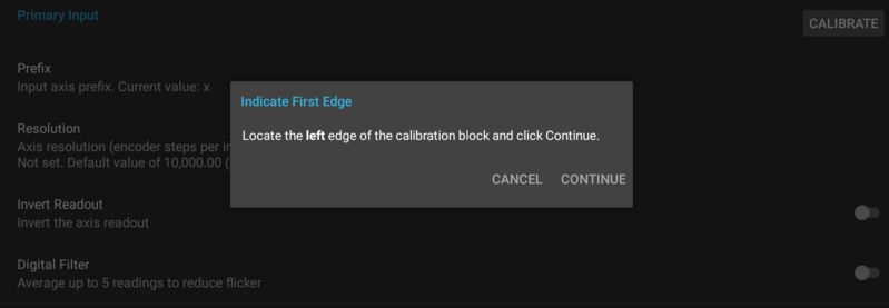
Once you have indicated the edge, press "Continue".

At this point, TouchDRO will sample the output from the scale for 10-30 seconds. This is done so the application can determine if the scale readout is stable and average the reading in case there is some jitter (that is common for iGaging EZ-View and DigiMag scales). Once the sample has been processed, the calibration will proceed to the next step automatically.
Step 4
The "Indicate Second Edge" dialog will be shown that will instruct you to indicate the edge that is farthest from the origin. Similarly to the "Indicate First Edge" dialog, it will depend on the machine type and the axis.
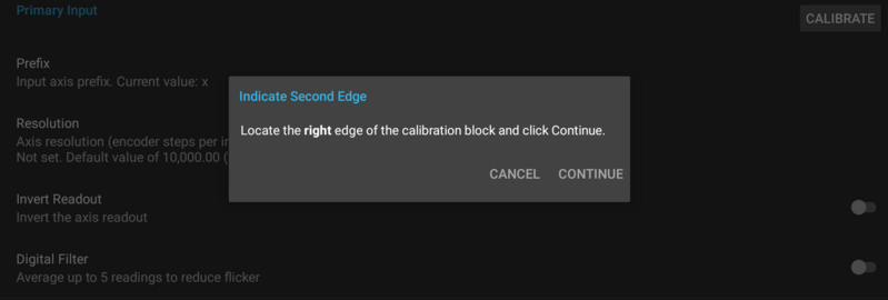
Once the edge is indicated, press "Continue".
TouchDRO will again sampe the scale output, similar to Step 3, and proceed to the next step.
Step 5
If the calibration went OK to this point the application will calculate the resolutions (encoder steps per Inch and microns per step) and display a confirmation dialog shown below. Press "Apply" to set the CPI; if the axis is inverted, the application will also turn on the "Invert Axis" setting.

This concludes the calibration for the first axis input; now you can repeat this process for any remaining inputs.
Angular Axis Calibration
Angular axis calibration procedure differs from the linear axes. It doesn't require any calibration block and instead relies on counting full revolutions of the calibrated device.
Step 1
Click the "Calibrate" button next to the Angular axis primary input. This will bring up the "Indicate First Position" dialog. Rotate the axis to its 0 degrees mark and press "Continue".
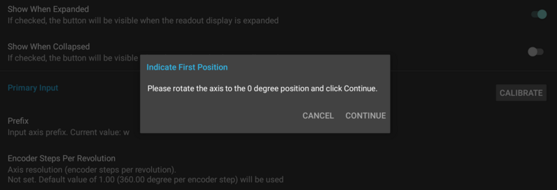
TouchDRO will sample the encoder readings for 15-30 seconds and if successful, will proceed to the next step.
Step 2
Rotate the axis by the number of revolutions indicated in the "Indicate Second Position" dialog. To eliminate any potential backlash, make sure to rotate the axis in the indicated direction and stop at the 0 degrees mark. When done, click "Continue".
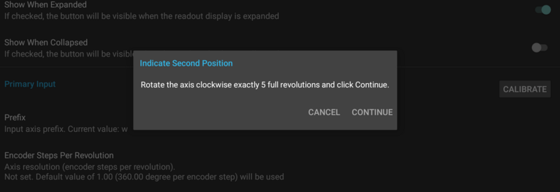
Similarly to the previous step, the application will sample the encoder for 15-30 seconds and will proceed to the next step.
Step 3
If the readings were successful, TouchDRO will display a dialog that lists axis resolution in encoder division per revolutions and the number of degrees per encoder division.
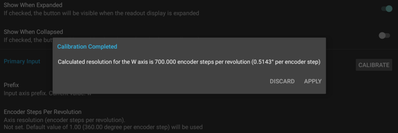
If the results look OK, press the "Accept" button. This will set the CPR value for the axis and if applicable, will invert the readout.
Tachometer Calibration
There is no built-in way to calibrate the tachometer at this time. Instead, if desired, an external tachometer can be used as a reference.
Step 1
Start the spindle and measure the RPM using a reference tachometer
Step 2
Compare the reading with the TouchDRO tachometer reading. If the readings are different, adjust the CPR value up or down and re-check the results.
The value can be adjusted by trial-and-error. I.e. if TouchDRO reads high, increase the CPR; if it reads too low, decrease the CPR. Alternatively, you can use the following formula:
Actual CPR = Current CPR * (Actual RPM/Current CPR)
