TouchDRO Graphical View Display
Overview
Graphical view displays 2-dimensional representation of the current workspace and provides a convenient way to perform some common machining tasks. In particular, it provides a fast and easy way to visualize and navigate a complex layout. In graphical display mode, TouchDRO has the ability to auto-select nearest sub-datum based on the real-time spindle position, automatically switch mill radius compensation direction, and toggle audible near-zero warning.
Horizontal Orientation
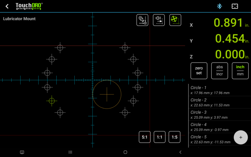
When the tablet is in horizontal orientation, the stand-alone graphical view display can be accessed via the "Switch View" button in the upper-right corner of the TouchDRO screen. The screen is split into two sections - wide left section that contains the projection view and a narrower side panel that includes a small 3-axis readout display and the Saved Sub-Datum list, similar to that on the main display.Vertical Orientation
In vertical orientation, the graphical view is part of the maid TouchDRO display and occupies [approximately] the bottom half of the screen. Axis position readouts and Saved Sub-Datum List are shown in the upper half of the screen. Consequently, the Projection View takes up the full width of the screen.User Interface Elements
Axis Readout Display
Axis readout display is a stripped-down version of the readout display shown on the main TouchDRO screen. It includes up to three linear axis readouts (X,Y and Z) and the global Zero Set, Absolute/Incremental and Inches/Millimeters buttons. These work identical to the buttons that appear in the main display's function strip. Additionally, axis readouts are clickable: Short click brings up the Axis Details dialog Long-press brings up the Set Dimension dialogStored Sub-Datum List
Stored sub-datum list is a simplified version of the list shown on the main TouchDRO display.2D Projection View
2D Projection View displays the current 2D top-down projection of the current workspace. The plane of projection depends on the machine type defined in the application settings. On a milling machine (vertical and horizontal), the projection shows the X/Y plane and on a lathe, it shows the Z/X plane. The direction of the axis movement follows the convention where Z is in-line with the axis of spindle rotation and the other two axes are laid out using the "right hand" rule, as described in "DRO Coordinate Systems and Datums" resources/dro-manual/dro-coordinate-system-and-datums.html User interface elements and symbology differ between different machine types. Those differences will be noted below.Workspace Name
Current workspace name is displayed in the upper-left corner of the projection view. The name is non-interactable and is shown for information purposes only.Cursor/Crosshairs
Current spindle position [on a milling machine] and the cutter position [on a lathe] is represented by the crosshairs. By default, the auto-center mode is active. In this mode, the crosshairs span the whole width and height of the projection view display and stay centered, while other workspace elements move in response to the spindle/cutter movement. Depending on the default units (metrics or imperial) selected in the application preferences, the crosshairs are graduated in inches or millimeters. Panning or double tapping the screen deactivates auto-center mode. In this mode, the crosshairs are replaced by a smaller cursor that moves in response to the spindle/cutter movement, and other workspace elements remain stationary. The size of the cursor represents 2 inches in imperial mode and 20mm in metric mode. Pressing the Re-Center button re-activates the auto-center mode.Cutter Position
On a milling machine, when a tool is selected via the Tool Radius Compensation function, the projection will display the cutter, represented as an orange circle with small crosshairs in the middle. The position of the circle depends on the selected direction of the tool offset, and the size is proportional to the selected tool diameter. Tapping inside the circle brings up the offset selection widget that can be used to quickly change the relative position of the cutter to the workpiece. Long-pressing inside the circle will bring up the "Clear Tool Radius Compensation" prompt On a lathe, there is no equivalent function since tool offsets work fundamentally differently.Display Scale Buttons
The three Display Scale Buttons in the lower-right corner of the Projection View allow you to quickly change the scale of the display between 1:1, 5:1 and 1:5. Additionally, the display can be scaled using the 2-finger pinch gesture. Maximum and minimum scales are 10:1 and 1:10 respectively. Moreover, double-tapping the screen will scale and pan the display so all workspace elements fit on screen. In 1:1 scale, TouchDRO attempts to scale the dimensions such that 1 inch on screen corresponds to 1 inch of machine travel, but this is subject to some limitations. Namely, some devices don't report screen size/resolution correctly, which can throw off the display.Mode Toggle Buttons
In the upper right corner of the projection display, there is a group of buttons that turn on and off various modes.
- Auto-select Nearest Sub-Datum - when on, TouchDRO will automatically select the nearest sub-datum as the spindle moves. The activation distance is 0.25" or 6.35mm.
- Guide Proximity Warning - when on, proximity warning for the appropriate axis will be activated when a guide is selected. It works identical to the Near-Zero Warning that can be accessed from the Axis Details dialog.
- Auto Tool Offset (milling machine only) - when on and tool radius compensation is active, selecting a guide will change the tool offset direction such that the readout will display the position of the cutting edge nearest the selected guide.
Sub-Datums
Any sub-datums present in the workspace are displayed as circles that are about 0.25in/6.35mm in diameter with crosshairs that mark their center. Active sub-datum will be the same color as the primary readout display (yellow-green by default) and the rest of the sub-datums are white.
- Tapping a sub-datum selects/deselects it and deactivates the Auto-select Nearest Sub-Datum mode.
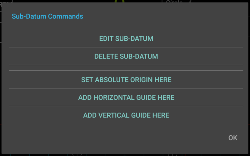
- Long-pressing a sub-datum brings up the "Sub-Datum Commands" dialog that has the following options:
- Edit Sub-Datum - brings up the "Edit Sub-Datum" dialog
- Delete Sub-Datum - brings up the "Delete Sub-Datum" dialog
- Set Absolute Origin Here - sets the absolute origin to the position of the selected sub-datum
- Add Horizontal Guide Here - adds a horizontal guide at the position of this sub-datum
- Add Vertical Guide Here - adds a vertical guide at the position of this sub-datum

Guides
Guides are represented as red lines that span the whole height or width of the projection view. The guides work as one-dimensional sub-datums. When a guide is activated, the incremental origin for the relevant axis is set to the position of the guides. Note that unlike saved sub-datum, deactivating the guide doesn't restore the previous incremental origin.
Depending on the currently active modes (see Mode Toggle Buttons above), selecting a guide can recalculate the cutter, offset direction, and activate the Proximity Warning function.
- Tapping a guide activates or deactivates it
- Long-pressing a guide brings up the "Delete
Guide" dialog

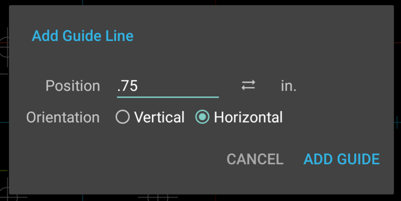
Guides can be placed at any arbitrary location by long-pressing anywhere in the employ area of the projection view or at a specific sub-datum location from the "Sub-Datum Commands" dialog (see above).
