Axis Details Dialog
Axis details dialog can be accessed by pressing the axis label button next to the relevant axis redout on the main DRO screen. The dialogs offer some additional information and access to axis-specific functions. The information shown depends on the type of the axis. In other words, X, Y, and Z details offer different information and actions than the angular α axis.
Linear Axis Details
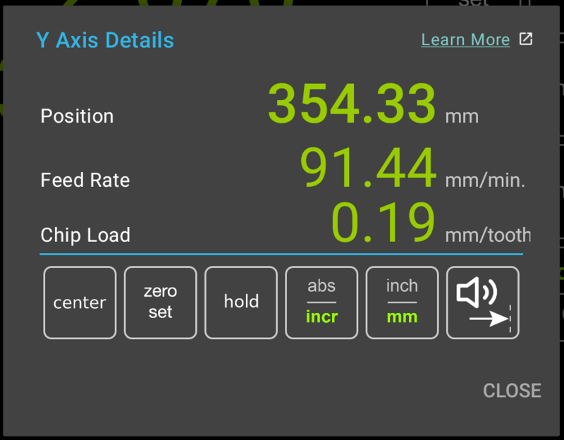
Linear axis readouts (X, Y, and Z) look similar to the screenshot below.

Readouts
Position
Position display is identical to the readout shown on the main DRO display.
Feed Rate
Feed rate is calculated using the change in position over time. It can be used to quickly verify or adjust the feed rate for the axis.
Chip Load
When a cutter is selected, the chip load is calculated using the current feed rate and RPM.
Action Buttons
Each of the action buttons below can be shown in one of the three configurable button positions on the main screen. In such a case, the buttons will have identical functionality.
Center Button
Center function is used to find the centerline of the workpiece. Functionally, it finds the half-way point between current position and the 0 point and sets the origin to the calculated value.
To set find the centerline, follow these steps:
- Indicate one edge of the workpiece (there is no need to account for the edge finder diameter)
- Press "Zero Set" button
- Indicate the opposite edge of the workpiece
- Press the "Center" button
- Exit the Axis Details dialog
By default this function uses the incremental coordinate system. In order to set the absolute origin to the center point, long-press the "Zero Set" and "Center" button, which will apply the action to the absolute coordinate system.
Zero Set Button
Zero set button sets the zero point to the current position. The button has two functions:
- Short press - sets the incremental origin to the current position and switches the axis to incremental mode
- Long press - sets the absolute origin to the current position (after displaying a confirmation dialog)
Hold
Hold function is used to quickly switch cutters without losing current axis position. It works by freezing the axis readout. The function affects the currently selected coordinate system for the axis but, in most cases, the function should be used in Absolute mode.
An example workflow can be as follows (using Z axis with a manual tool height setter as an example):
- Place the tool height setter under the cutter
- Lower the cutter onto the contact area until the gauge reads "0"
- Press the "Hold" button; the readouts will turn gray, indicating that position refresh is paused
- Mount the new cutter into the spindle
- Lower the new cutter until the gauge reads "0"
- Press the "Hold" button; readout will turn green, indicating that position refresh has resumed
To cancel the Hold function, long-press the Hold button. This will resume position refresh without altering the position.
Absolute/Incremental Mode Selection
The "abs/incr" (Absolute/Incremental) button switches the axis between the two coordinate systems. If a sub-datim is active, switching to the Absolute coordinate system de-activates the sub-datum.Inch/mm Selection
The unit selection button switches the axis between metric and imperial units.Near-Zero Warning
This button activates audible near-zero warning. The function works as follows: When axis readout moves to within 0.100" from the 0 point (from either direction), the DRO will start emitting periodic beeps The frequency of the beeps increases as the distance to the 0 point decreases Within 0.005" from 0, the DRO will start emitting a solid beep When the readout is at 0, the continuous beep stops Please note: When the axis is not moved for 5 seconds, audible warning stops; it resumes when the axis starts moving again. When the direction of the movement changes (i.e. axis is moved away from 0), audible warning stops. Once 0 is reached, axis must move 0.005" from 0 for the warning to be re-activated Near-Zero warning can be active for a single axis at a time. Activating the function for an axis will automatically deactivate it for any other axis, if applicable.Angular Axis Details
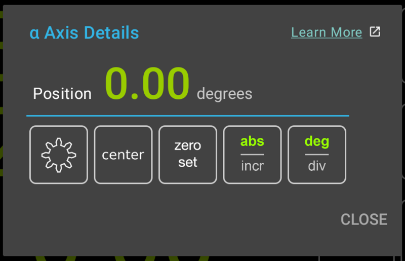
Angular axis details dialog is similar to the linear axis details, as shown below.
Position Readout
Position readout displays the axis readout, identical to the main screen.Action Buttons
Center, Zero Set, and Abs/Incr buttons provide the same functionality as in the case of linear axis details dialog and are described in the previous section.
"Gear" Button
The "Gear" button (AKA "Divisions Per Rev." command button) is used to set the Angular axis to display arbitrary divisions. Most commonly, this function is used for cutting gears, indexing plates, etc. via a rotary table [equipped with an encoder].
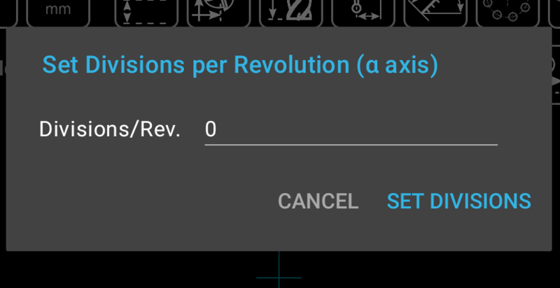
Pressing the button brings up the "Set Divisions Per Revolutoin" dialog shown below.

Degree/Division Selection
This button switches the angular axis display between degrees and arbitrary divisions set via the "Gear" function.
