Glass/Magnetic Scale Adapter Quick Start
TouchDRO Adapter for Glass and Magnetic Scales comes with a Deluxe Kit that includes a 3D-printed enclosure, no-solder D-Sub connectors and all the necessary hardware, or just the adapter board and a set of standard D-Sub connectors.
To complete the final assembly of the Deluxe Kit, you will need to configure the D-Sub connectors to match your scales' pinout and screw together the enclosure. Start-to-finish, this process usually takes between 15 and 30 minutes and requires only basic tools, such as:
- Philips #1 screwdriver
- Small needle-nose pliers or a 3/16" wrench (5mm works as well)
- Clippers
- Tweezers (optional)
To complete the setup of your TouchDRO Adapter for Glass and Magnetic Scales, you will need to configure the scale connectors to match your scale's pinout and mount everything into the enclosure using the provided hardware.
Kit Contents
Your Deluxe TouchDRO adapter kit includes the following parts:
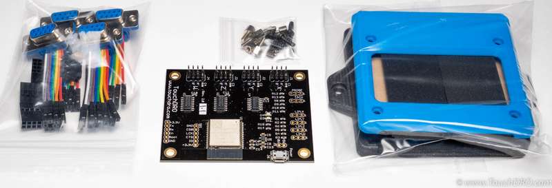
- TouchDRO adapter main board
- 3D printed enclosure kit with hardware
- Four female D-Sub 9 connector assemblies
- Four 4x2 pin 0.1" female connector housings
To complete the setup, you will need to provide a 5V Micro-USB power supply (a Micro-USB phone charger is recommended), a set of compatible scales, and an Android tablet that meets TouchDRO system requirements .
Assembly Instructions
Connector Configuration
TouchDRO ships with four D-Sub connectors with pre-crimped wires and four 4x2 0.1" connector housings. Each connector assembly includes the components shown below.
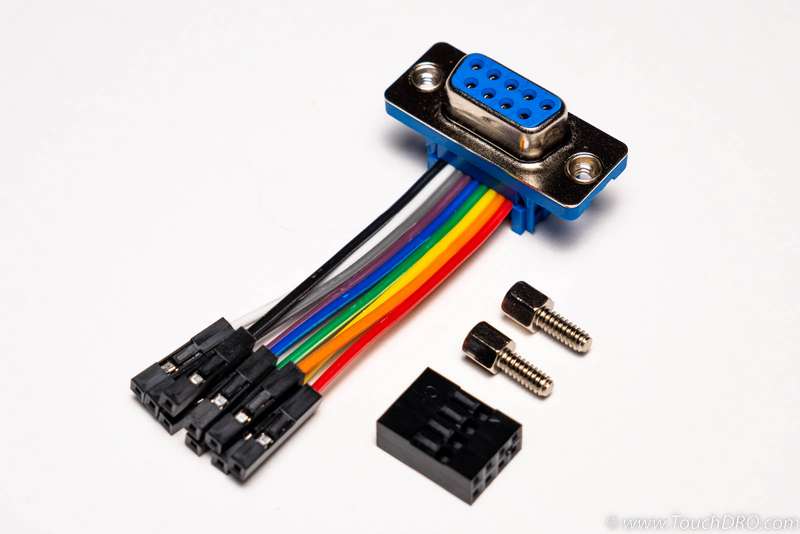
Since glass and magnetic scales come with many different pinouts (there is no standard), you will need to configure the connectors to match your scales.
Using the pin function diagram provided with your scales, locate the 5V, 0V and data pins (A and B for "single-ended" scales, or A, A', B, B' for "differential" scales).
Your scales might have pins labeled R or Z. Those are "reference" pins and are not used by TouchDRO, so you don't need to connect them to anything.
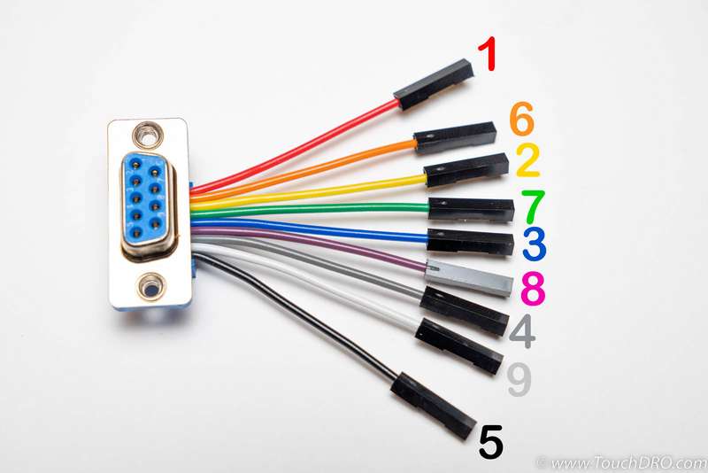
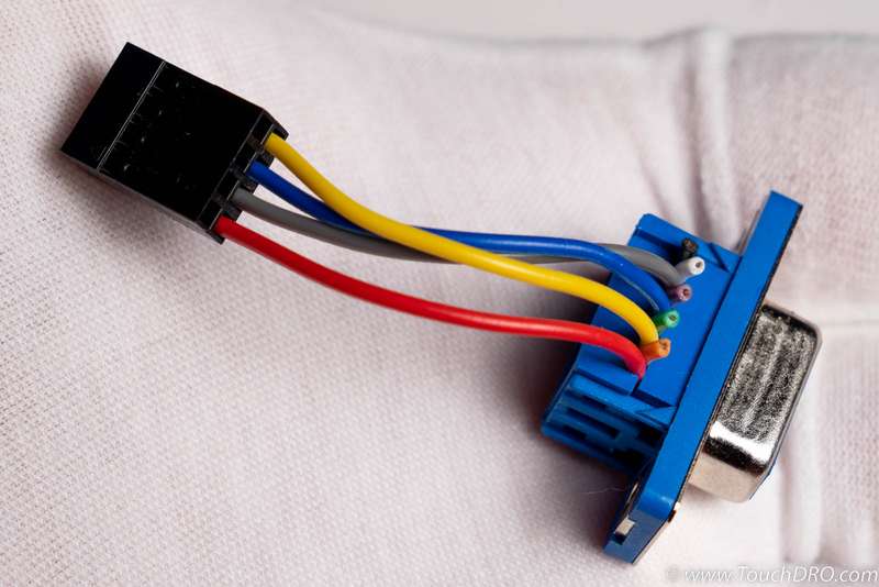
The D-Sub connectors supplied with TouchDRO come with pre-crimped 9-conductor "rainbow" ribbon cable with individual wire housings. Using the photo below, find the colors for each of the relevant lines (A, B, 0V, Gnd, etc.).
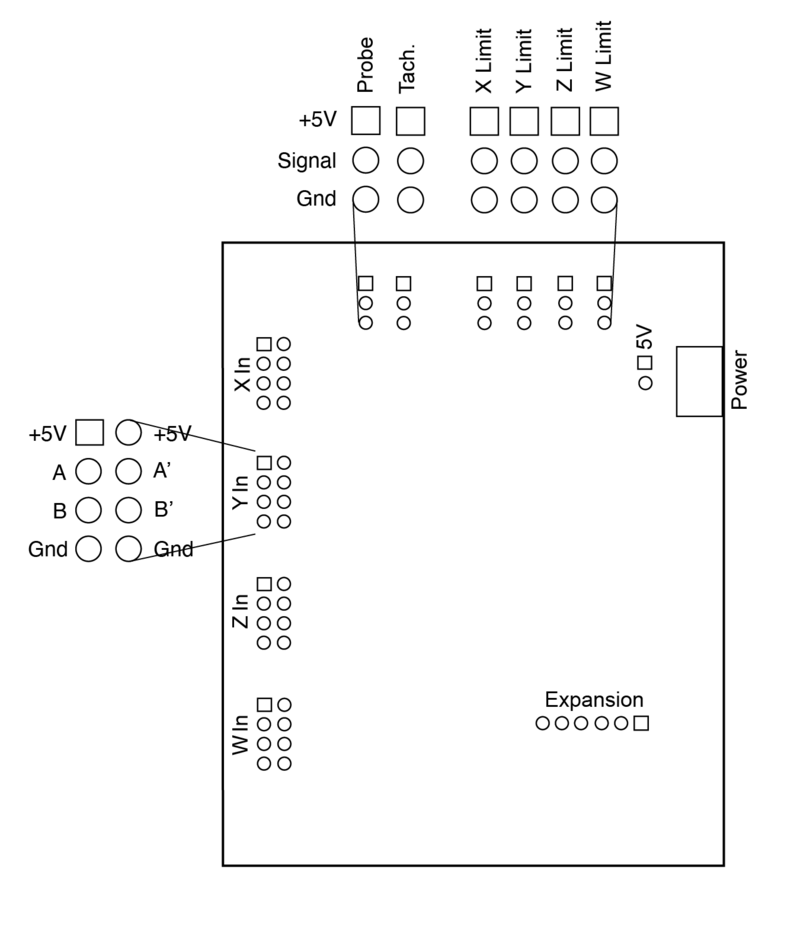
The pinout of the 4x2 connector is shown in the diagram below.:
Smoke Test
Chinese scales often include incorrect documentation; therefore, before finalizing the connector assembly, let's check that the pinout is correct and TouchDRO can read the scale. To do so, plug in 5V, Gnd, A and B lines into the board (ignore A' and B' for now), place the board on a non-conductive surface and power it up.
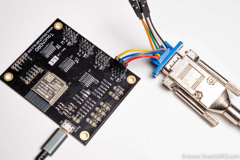
If you haven't installed the TouchDRO application, you can download and install it from the Google Play Store or Amazon Appstore. For instructions for connecting to the adapter, please refer to the Connecting To TouchDRO Scale Adapter User Manual page.
Once connected, move the scale's reading head and see if the numbers on the TouchDRO display change. If everything goes well, you should see the numbers increasing as you move the head in one direction, and decreasing as you move in the opposite direction.
If your scales use differential output, you can now connect the A' and B' lines and re-check for correct behavior.
If you don't see any movement, or the number is stuck jumping up and down, the connection is incorrect. Power down the adapter and check the scale pinout. You might need to open the male connector housing and compare wire locations to the provided scale documentation. If the documentation doesn't match the connector, you will need to reverse-engineer the pin functions using the instructions described on the How to Find Glass DRO Scale Pin Functions page.
Finish Connector Configuration
You can use the wires as is, since they come with individual pin housings already installed, but it's better to use the provided 4x2 hosings instead. The 4x2 connector will have a more solid connection and will generally be more convenient if in the future you need to unplug the scales.
To remove the existing wire housings, use a set of sharp tweezers, an Exacto knife or even a large needle to lever up the tab as shown in the photo below and pull the wire out. You should feel almost no resistance; pulling too hard might damage the wire.
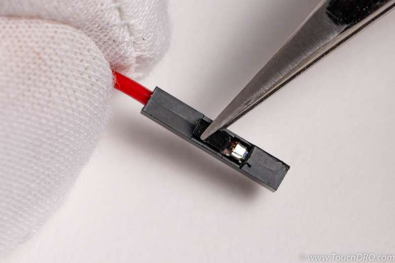
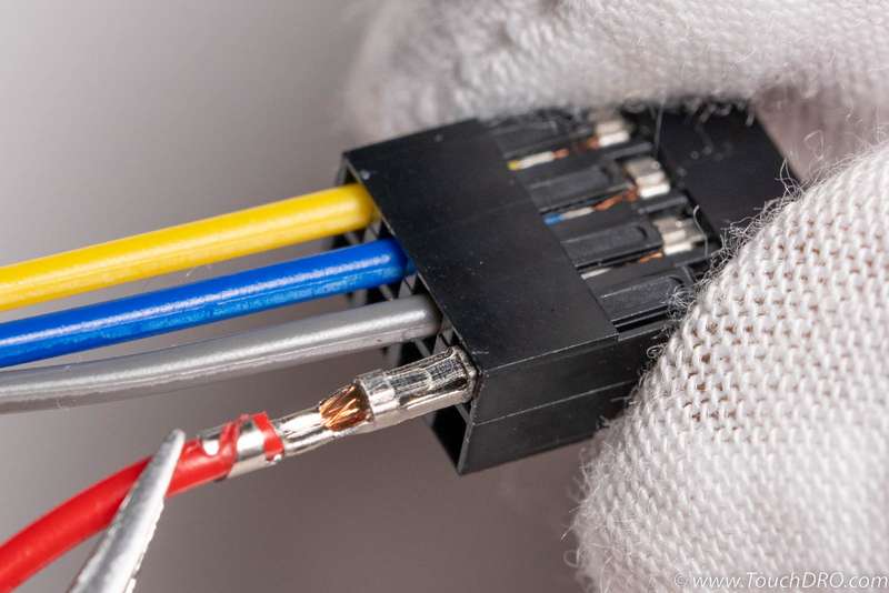
Insert the wires into the 4x2 housing with the crimped terminal as shown below (the direction matters here).
You will be left with a few wires that are not used for any scale connections. Using a pair of clippers, carefully cut the unused wires as close to the D-Sub connector body as possible, being careful not to damage the adjacent connections.
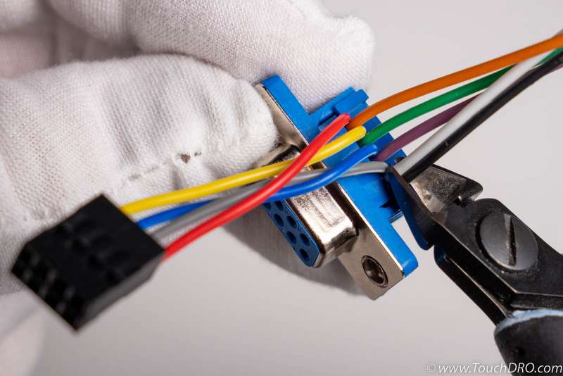
The end result will look similar to the photo below.
Enclosure Assembly
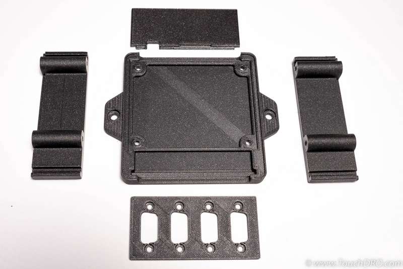
The bottom part of the enclosure consists of the five parts shown in the photo.
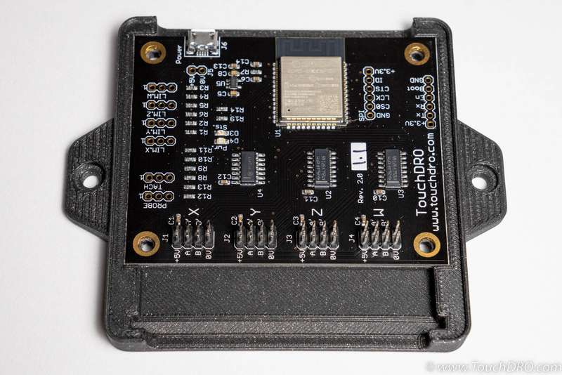
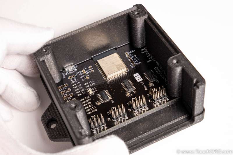
Start by pressing the main board into the bottom of the enclosure. It should be a snug fit so you will need to firmly press on the edges of the board until you feel it snaps into place.
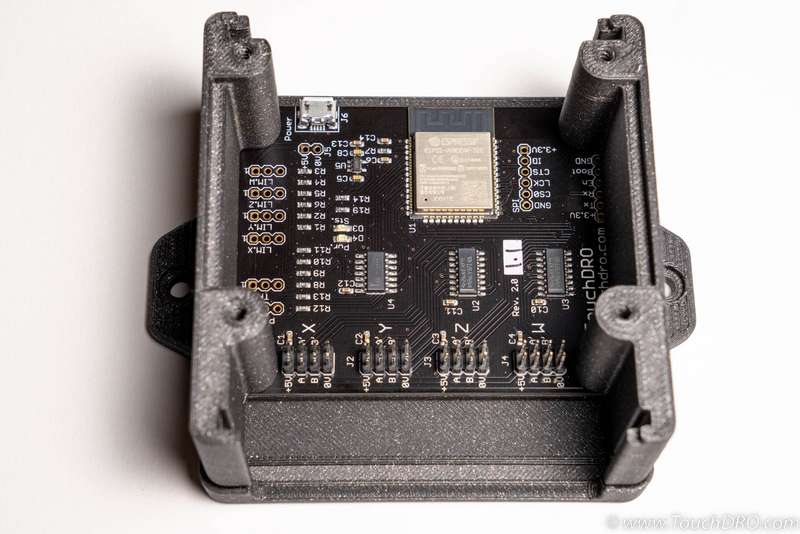
Using four provided self-tapping screws, attach the two side pieces to the bottom part as shown below. Note that the cutout is facing up (it is there to hold the clear plastic insert). Get the screws snug, but don't tighten them completely yet. You will need to have a bit of movement to allow the front and back to slide freely.
Push the back panel into it's slot as shown below.
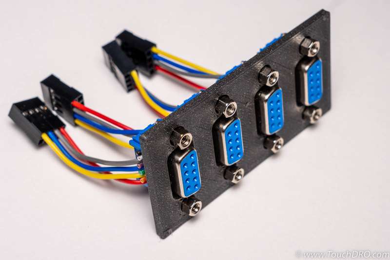
Attach the D-Sub connectors to the front panel using the provided hex standoff screws.
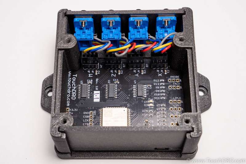
Next, plug in the 4x2 connectors into the main board making sure that you keep the correct connector polarity.
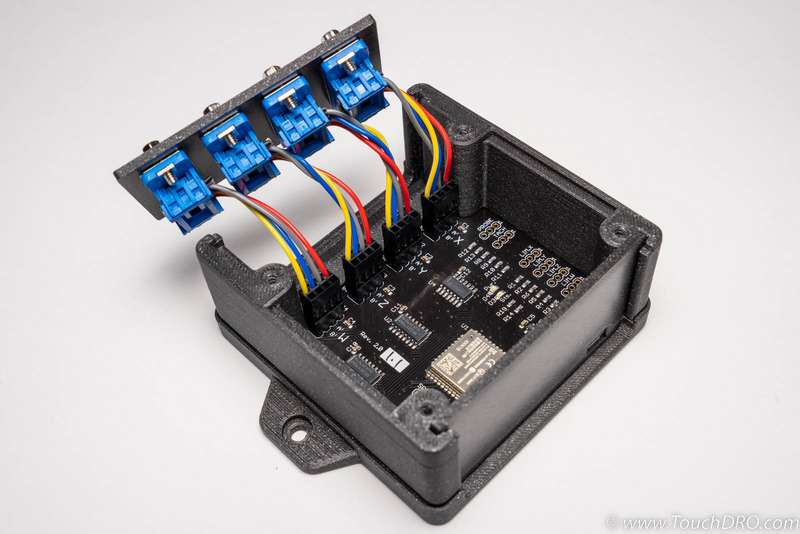
The wires are long enough to allow the front panel to clear the sides of the enclosure. Grab the front panel by the edges and carefully push it into its place.
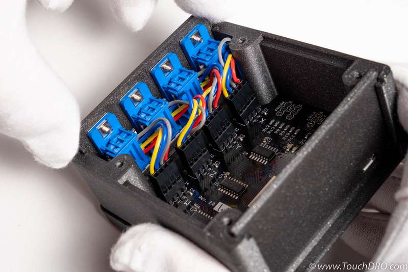
Note that there is just enough clearance between the connectors and the sides for the wires to fit in. Make sure the wires are not catching anything, and don't push too hard, or you might damage the connector assembly. Fully inserted, the front panel will look similar to the photo below.
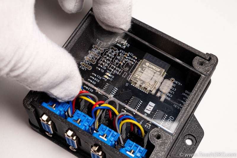
The lid consists of two parts - a clear acrylic insert that allows you to see the status LEDs when the board is powered up, and the blue top that holds it in place.
Start by peeling off the protective paper from the insert and place it into the recess, as shown below.
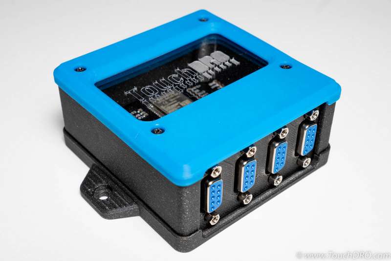
Now place the blue lid cover and fasten the four self-tapping screws. Finally, snug up the screws on the bottom of the enclosure, and you are done with the adapter assembly. The finished product should look similar to the unit in the photo below.
Next Steps
At this point, you should have a working TouchDRO Adapter for Glass and Magnetic scales. Before you can use your new DRO setup, there are a few remaining important steps you will need to complete (besides mounting everything onto your machine).
First of all, you will need to configure the TouchDRO application for your specific use case. TouchDRO's user interface is very flexible, so you will be able to set it up to fit your workflow and personal preferences. If you haven't used TouchDRO before, take a look at the Tour of TouchDRO User Interface page and the TouchDRO Initial Configuration
Second, it's recommended that you calibrate the scales in place. Even if you know the nominal resolution of your scales, calibration will take care of any linear error introduced by manufacturing tolerances. Detailed calibration instructions are described on the TouchDRO Input Calibration User Manual page.
