TouchDRO Reference Image Overlay
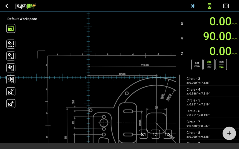
The Graphical Layout Display in TouchDRO Plus has the ability to set a CAD drawing or a photo as a reference background for the workspace.

The reference image can be a drawing exported directly from CAD software, or a photo of a part taken with the tablet's camera. The image can be precisely aligned and scaled to match the machine coordinate system, and can be used as visual guide when machining a complex part, or even as a virtual layout that can be used to locate workpiece features.
User Interface Overview
The Reference Image Overlay function can be accessed from the toolbar on the Graphical Layout Display screen:
- The "Camera" button brings up the default Android camera application that can be used to take a photo of an existing workpiece.
- The "Image" button is used to load a CAD drawing or an existing photograph from the file system. Tapping the button will bring up the default Android file browser that will let you select a JPG or a PNG file.
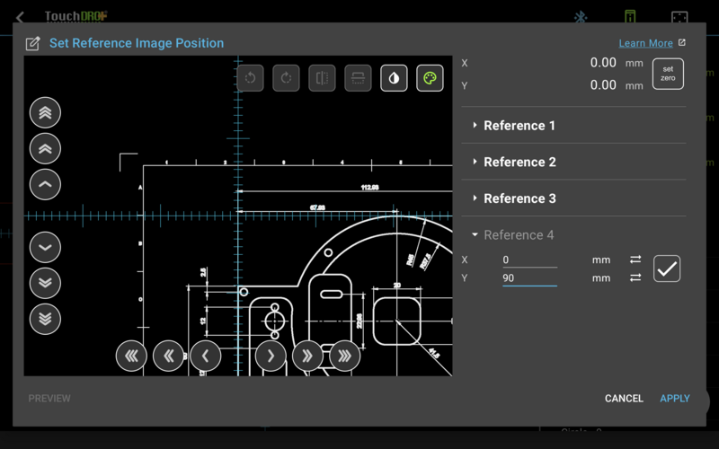
Once the image is selected, TouchDRO will display the "Set Reference Image" dialog, as shown below.

This dialog is used to prepare the image for use as a layout reference. It allows some basic manipulations, such as rotation, mirroring, and basic appearance changes, but the primary function is to calibrate the image to the machine coordinate system.
Image Preview
Majority of the screen is taken up by the Image Preview area that is used to preview (and align) the image. Inside the preview area, you can move the image around and zoom in/out using the drag and pinch gestures. For fine position adjustment, you can also use the buttons located along the left and bottom edges of the preview area.Image Preparation Buttons
Along the top edge of the preview area you will find a series of buttons that are used to manipulate the image. From left to right, the buttons are:- Rotate left - rotates the image left by 90 degrees
- Rotate right - rotates the image right by 90 degrees
- Flip horizontally - flips the image horizontally (creates a mirror image)
- Flip vertically - flips the image vertically
- Invert colors - inverts image colors (creates a negative image)
- Remove color - converts the image to grayscale
Position Readout
The Position Readout panel is displayed in the upper right corner of the window in landscape orientation, or in the lower left corner in portrait orientation. The panel displays absolute position readouts for the axes that are appropriate for the current projection machine type.
Additionally, it contains the "Set Zero" button that can be used to set the absolute origin for the two axis readouts.
Reference Points Panel
The Reference Points panel appears either on the right side of the dialog, or underneath the Image Preview Area, depending on the screen orientation. It contains four identical sections that are used to set up to four reference points.
Each reference point section contains two edit text boxes where you can enter the real-world coordinates for the given reference point. Next to each edit box, there is a "Synchronize" button that will copy the current absolute spindle/tool position into the edit box.
The "Check Mark" button to the right of the edit boxes locks the position of the reference point. When the position is locked, the button caption switches to "Clear" mode (displays a trash can icon). Tapping it will clear the reference point coordinate.
How to Use
To set a reference background image, follow these steps:
- Tap the "Camera" button or the "Image" button to take or select an image
- Align the first reference point under the crosshairs
- Enter the physical position for the selected point
- Tap the "Set" button
- Repeat steps 2-4 for the other reference points. Four points are required if the image has any perspective distortion; for a rectilinear image only two diagonally opposed points are needed.
- Tap the "Preview" button to check the un-distorted image
- Tap the "Apply" button to set the background
For a more in-depth How-to guide, please refer to the "Using the Reference Image Function" page.
When the background is set, the "Camera" and "Image" buttons are hidden, and the "Background" button is shown.
- Short tap will toggle the background display
- Long-press will clear the background image (after showing a confirmation dialog)
