TouchDRO Arbitrary Hole Circle Function
The Arbitrary Hole Circle function is very similar to the Bolt Hole Circle function but instead of creating holes that are spaced equally, it can be used to create a set of holes with arbitrary spacing.
The function has two modes - Basic and Advanced:
- Basic mode can be accessed by pressing the "Arbitrary Hole Circle Function" button in the function strip or "Arbitrary Hole Circle" on the "Add Sub-Datum(s)" menu
- Advanced mode can be accessed by long-pressing the "Arbitrary Hole Circle Function" button in the function strip or "Arbitrary Hole Circle" on the "Add Sub-Datum(s)" menu.
Basic Mode
In basic mode, the function will create a circle in the machine's default projection plane with the center located at the current spindle/cutter position (current absolute position for the relevant axes).

Default Projection Planes
The project plane is set as follows:
- Milling machine - XY, 0.0 degrees parallel to positive X direction
- Lathe - XZ, 0.0 degrees parallel to positive Z direction
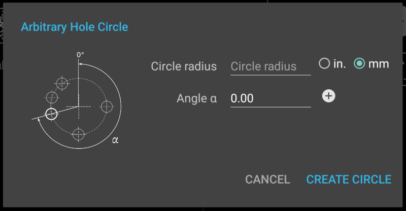
The function accepts the following parameters:
Circle Radius
Circle radius can be any positive decimal number or an arithmetic expression. This value is required.
Circle radius dimension can be set in inches or millimeters regardless of the currently selected axis units. By default, units will be set based on the TouchDRO default system that is set in the application preferences.
Hole Angle (α)
Hole angle field, in conjunction with the "+" button is used to add between 2 and 100 holes at arbitrary angles. The field can accept decimal values between -360.0 and 360.0, as well as basic arithmetic equations.
Advanced Mode
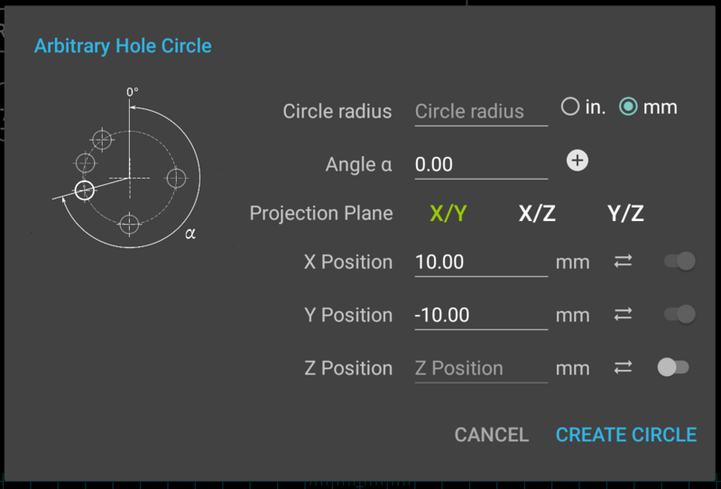
In advanced mode, the Arbitrary Hole Circle function offers more control over the projection plane of the Bolt Hole Circle, position of the center, and the value of the third axis.

In advanced mode, the function accepts the following additional parameters:
Projection Plane
Machine plane on which the circle will be created. Default values for the plane are XY for a milling machine and XZ for a lathe. Starting angles are set as follows:
Milling Machine
- XY - 0.0 is parallel to the positive Y direction
- XZ - 0.0 is parallel to the positive Z direction
- YZ - 0.0 is parallel to the positive Z direction
X/Y/Z Positions
X, Y, and Z Position fields define the location of the Bolt Hole Circle in two or three dimensions. Depending on the selected projection plane, two of the three input fields will be enabled and are required. The third field is optional and can be enabled if desired.
By default, enabled fields are pre-filled with the current readings for the relevant axes. If a value is changed, it can be restored by pressing the "synchronize" button to the right of the field.
Units for each field are set to the current units for each individual axis.
How To Use
Drill Three Pairs of Holes
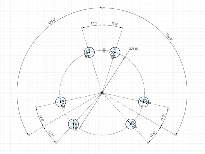
Goal: drill three pairs of holes, as shown in the sketch below.

- Bring up the "Arbitrary Hole Circle" function
- Enter 25/2 into the Circle Radius field
- Click on "mm" radio button to switch to millimeters (if needed)
- Enter the following values into the "Angle α" field; press the "+" button after each entry:
- -17.5
- 17.5
- 120-17.5
- 120+17.5
- -120-17.5
- -120+17.5
- Press "Create Circle"
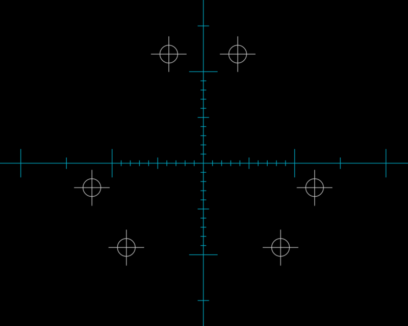
The result will look similar to the screen fragment below:

