Glass Scale Adapter Enclosure Build Instructions
The enclosure for the TouchDRO Adapter for Glass and Magnetic Scales V2 is sold as a DIY kit. It consists of a set of black cast acrylic cutout parts that make the enclosure body and a clear enclosure lid. It also includes a set of screws, nuts, and standoffs needed to hold the PCB in place, mount the D-Sub connectors, and close the lid.

Tools and Materials
As mentioned earlier, the enclosure is sold as a DIY kit and is designed to be glued together. In order to complete the assembly, you will need the following tools and materials:

Glue
The enclosure is made of cast acrylic that can be welded using thin Acrylic Cement. Alternatively, the enclosure can be glued using thin Super Glue (Cyanoacrylate adhesive). The main advantage of Acrylic Cement is the fact that it fuses the mating surfaces by chemically melting the plastic, so the bond is as strong as the base plastic, and the results are generally cleaner. Superglue, on the other hand, works like a traditional adhesive, so the bond is a bit less strong. The main advantage is the price and availability.
Acrylic cement can be purchased from any plastic supply house or a local hardware store for about $7 for a jar; most supermarkets and many convenience stores carry thin superglues for as little as $1 for a small container. Generally speaking, unless you intend to glue acrylic in the future, using Superglue is much more cost-effective and the results are pretty close. Just make sure that you use very thin cyanoacrylate glue and not the gel version.
Applicator Bottle
In order to apply Acrylic Cement to the mating surfaces, you will need an applicator bottle. You should be able to find one at any plastic supply store; general hardware stores might carry these bottles as well, but it's a bit hit-and-miss.
Rubber Bands
In order to hold the pieces together while applying the glue, you will need a few rubber bands.
Tooth Picks
Acrylic cement and thin Superglue can mar the surface or glue the rubber bands to the enclosure if they touch the joints. To avoid this, you will need four toothpicks, matches, or similar sticks to keep the rubber away from the glue.
Screw Driver, Pliers, etc.
Finally, you will need a #1 or #2 Phillips screwdriver and a pair of needle-nose pliers.
Gluing Enclosure Body
The body of the enclosure consists of the parts pictured below. Note that the parts in the picture are cut out of different color acrylic for illustration purposes; the actual enclosure is opaque black with a clear lid.

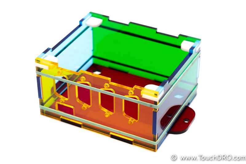
The first step is to glue the walls [yellow, green, and blue pieces] of the enclosure to the bottom piece [red]. This operation can benefit from having a helper who can hold the pieces together while you stretch the rubber bands around the sides. Once the box is held together with rubber bands, insert the four [white corner pieces], since you won't be able to do it once the sides are glued. The result should look similar to the picture below.

Please note that the sides [blue] and the back [green] are symmetrical front-to-back, but not top-to-bottom; the front [yellow] is not symmetrical in either direction.
If you pleased the rubber bands similar to the picture above, you will notice that they span the glue joints on the sides. This will pose a problem since the capillary action will draw the thin glue under the rubber band, which will mar the surface and/or glue the rubber band to it. This is where the toothpicks come in handy: you can use them to space the rubber bands away from the glue joints, as shown below.

You will notice that there are small gaps between the panels. This is a side effect of a small burr left by the lazer cutter, which is a "happy accident" in this case since it provides some space for the glue to be drawn into, which is desirable when using super glue. These gaps will disappear once the Acrylic Cement melts the plastic and the rubber bands draw the sides together or the super glue fills them.
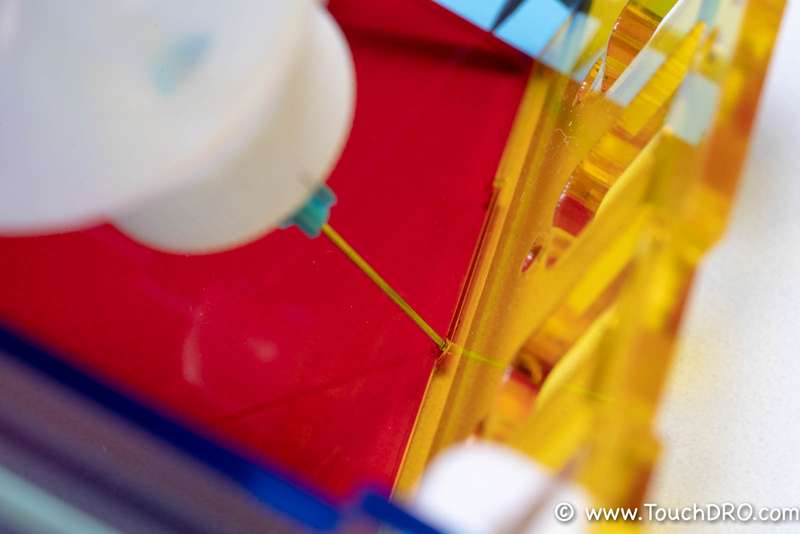
To apply the glue, hold the enclosure by its sides, making sure that your fingers don't touch any of the joints, and drip a small amount of glue into the corners from the inside. You will notice that the thin glue flows along with the corner and the capillary action draws some amount into the joint. Rotate the enclosure while adding small drops of glue until all of the joints are wetted with Acrylic Cement or a small fillet is formed by the Superglue.

Let the enclosure sit until the glue cures and carefully check that all of the joints have been properly glued; if not, add a bit of glue to those areas. Once done, it's time to glue in the PCB support and standoff. Front of the PCB is supported by the flat piece [amber] that is glued to the front wall of the enclosure; the back is supported by the [black] 3/16" standoff glued to the bottom. Now that the enclosure is glued, those pieces should fit pretty snugly; if you feel too much resistance though, sand off a bit of acrylic off the ends to avoid cracking the enclosure body. Glue those pieces using the same technique as before. The end result will be similar to the picture below.


Installing The Electronics
The order of operations for mounting the PCB, installing DB-9 connectors, and inserting the pins described in this section is completely optional, but doing it in this sequence will make the process less fiddly.
Attach D-Sub Connectors
D-Sub connector housings are attached to the enclosure using a set of 4-40 studs that are threaded into matching nuts on the inside. Getting to the bottom nuts is a bit fiddly, so the front board support has half of the nut profile cut into it, which will prevent the nuts from spinning while you are tightening the studs.
The mounting holes in the connectors are oversized, as are the openings in the enclosure. Consequently, the connectors have a bit of side-to-side play. If you prefer the connectors to be straight and parallel, it's best to tighten the bottom studs while leaving the top studs snuggled up. The connectors can then be tweaked a bit before the top studs are tightened.

Please note that the top nuts need to be turned such that the top side is parallel to the edge of the cover, or the cover will not sit flat.

Mount the PCB
The PCB is held in place by the support piece in front and two M3 screws in the back. To fit the board into the enclosure, tilt it so the edge with the Micro-USB connector is inserted first and then lower the other side. Once it's in the enclosure, you can guide the edge into the front support by grabbing the axis input headers (but being careful to avoid bending them).
Once the board is in place and the read mounting holes are aligned, you can use the two provided M3 screws and nuts to fix it in place.
Assemble the Cables
Once the PCB is in place, it's time to assemble the cables. Depending on the type of your scales, you will use either four or six wires for each cable. Start by inserting the ends with silver-colored terminals into the 8-pin Molex housing. Note that the terminals have a small tab that holds them in the housing; this tab needs to face the outside of the housing so that it can snap into the corresponding rectangular hole, as shown below.

Next, identify the scale input pins using documentation provided by your scale supplier. Beware that scales purchased off eBay, Alixpress, etc. often come with documentation that is incomplete or inaccurate. A quick way to "sanity check" the pinout is to take apart one of the scale connectors and see if the wire colors and locations match the diagrams in the manual. If not, you might need to refer to the article about "Finding Glass Scale Pinout".
Once you have determined the scale pinout, use your needle nose pliers to carefully push the gold plated terminals into the housings until you hear a positive snap.

Note that in order to remove the pins from D-Sub housings you will need a special pin extraction tool.
When done, plug the rectangular connectors into the PCB and test the scale to make sure you are getting position changes.

Close the Lid
The lid is held in place by four philips screws. The kit ships with four self-drilling screws that are originally intended for sheet metal, but due to their thread form they work surprisingly well for cast acrylic. The straight "drill" section of the screw fits into the lazer-cut hole without removing any material and provides a straight guide for the screw to allow it to cut clean threads in the plastic.
Further Modifications
If you decide to add limit switches, tachometer or probe input, you will need to drill additional holes in the enclosure. Since it's made of acrylic, drilling it is relatively easy on a drill press or a milling machine. To avoid cracks or blowouts, make sure that you have some sort of backing underneath, such as a piece of wood or plastic, and the part is held securely in place.
