TouchDRO DIY Kit Build Instruction
The DIY DRO kit is designed to be easy and straightforward to put together even if you don't have extensive soldering experience or deep knowledge of electronics. It uses relatively few components that are easy to identify. If you don't have a lot of experience building electronic circuits, please read Tips For Building a Reliable DIY DRO Circuit first. The page covers the tools and materials needed to build the kit and provides a lot of useful information about soldering and electronic assembly.
Key Points
- The kit is designed to work with multiple scale types. While the firmware takes care of protocol detection automatically, there are two settings per scale input that you will need to configure.
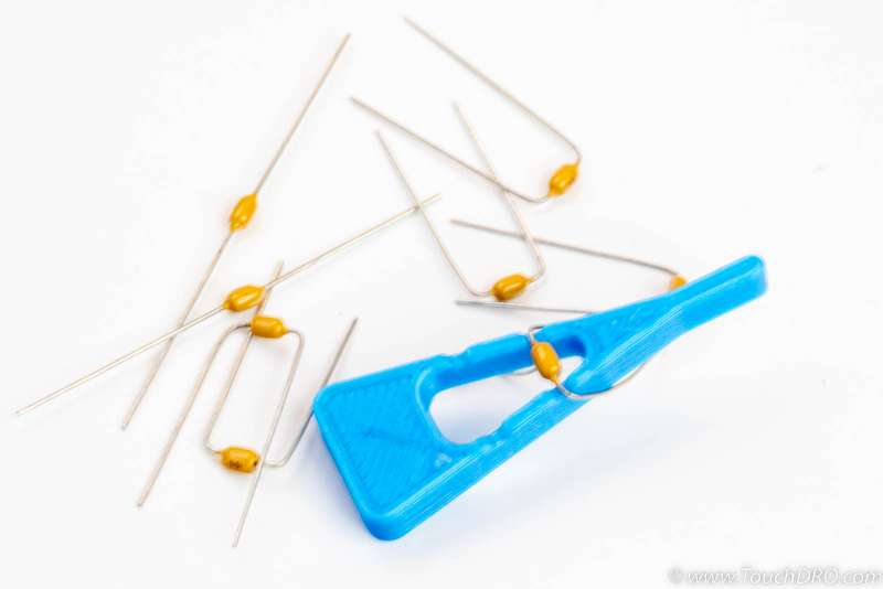
- Included with the kit is a lead bending jig shown below. It has two positions - shorter for the capacitors and longer for the resistors. To bend the leads you would simply place the part into the corresponding position and pull the leads downwards, as shown in the photo below.
- The ESP32 module comes programmed and fully tested. Before building the kit, it's a good idea to power up the module, connect it to the TouchDRO application, etc. before starting the build.
- The build order described below is just a suggestion. The main idea is that you will be adding parts in order of their height, so it's easier to lay the board flat while soldering. Other than that, the order doesn't matter.
Step 0 - Parts Inventory
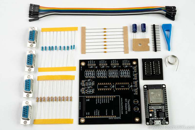
Start by sorting and identifying all of the parts in the kit. The Bill of Materials and list contents of your specific kit version can be found on the DIY TouchDRO Kit product page.
Step 1 - Configuration Jumpers
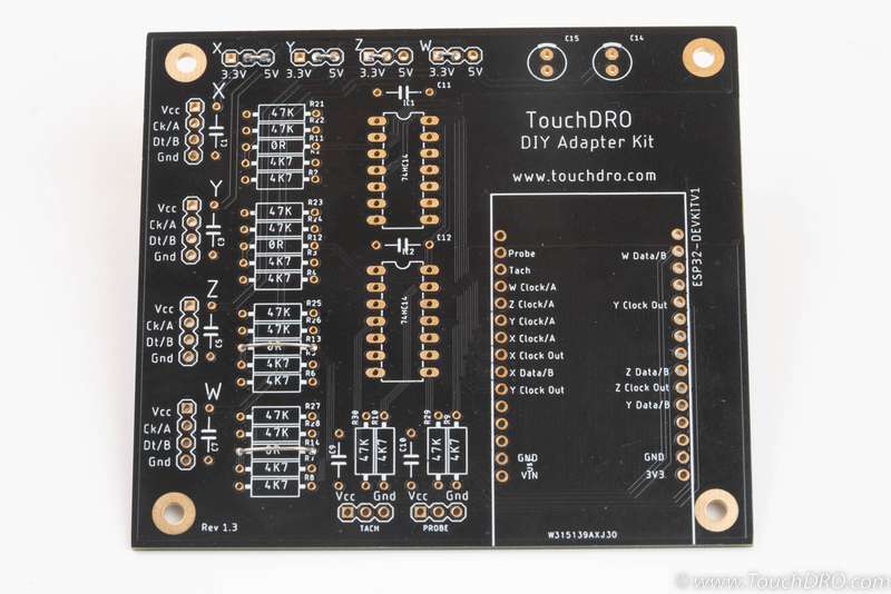
Each scale input needs to be configured for your particular scales. The first configuration is the supply voltage. Along the top edge of the board there are four sets of jumpers that set the supply voltage for each scale.
In the kit you received a short length of tinned buss wire. As shown in the photo below, make two full turns around the lead bending jig. Using wire cutters, cut the loops in half to create the 0.1" jumpers.
For standard Glass and Magnetic DRO scales, the jumper has to be in the 5V position; for capacitive scales it should be in 3V position. In the photo below X and Y are set to 5V, Z and W are set to 3.3V.
In addition to the voltage selection jumpers, iGaging 21-bit scales need to have their clock lines connected to the "CLOCK OUT" of the ESP32 module. This is done via a jumper in the R11, R12, R13, R14 position.
To make the jumpers, cut approximately 1" length of the buss wire and bend it in the "resistor" position of the lead forming jig.
In the photo below, Z and W inputs are configured for iGaging EZ-View DRO scales.
Step 2 - 0.1 uF Capacitors
Cut the capacitors off their tape and, using the short position on the lead bending jig, form the leads.
Insert the capacitors into the positions C1, C3, C5, C7, C9 - C12 (shown in the photo below) and bend the leads slightly outward.
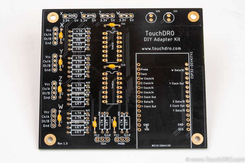
Solder the leads from the underside and clip-off the excess.
Step 3 - 4.7 KOhm Resistors
Cut the 4.7 KOhm [blue] resistors off the tape and form the leads using the longer position on the lead forming jig.
The resistors go into positions marked R1 through R10 (lower two positions next to each axis input and right positions next to the Probe and Tach. inputs). Solder the leads and clip off the excess. The end result should look like the photo below.
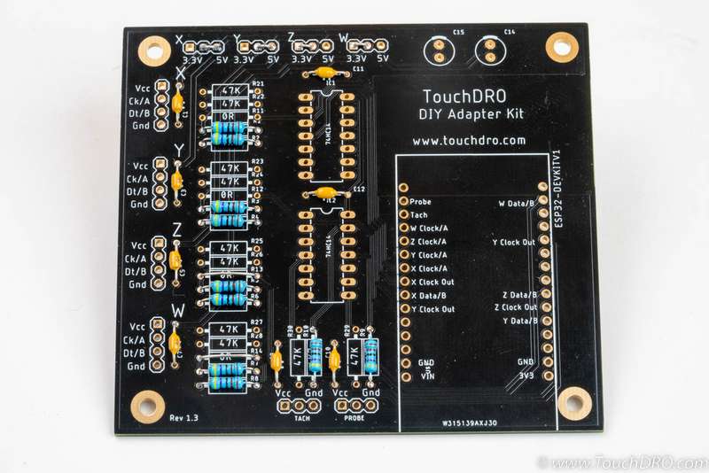
Step 4 - 47 KOhm Resistors
Cut the 47 KOhm [yellow] resistors off the tape and form the leads using the longer position on the lead forming jig.
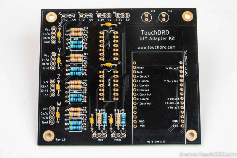
The resistors go into positions marked R21 through R30 (upper two positions next to each axis input and left positions next to the Probe and Tach. inputs). Solder the leads and clip off the excess. The end result should look like the photo below.
Step 5 - ICs
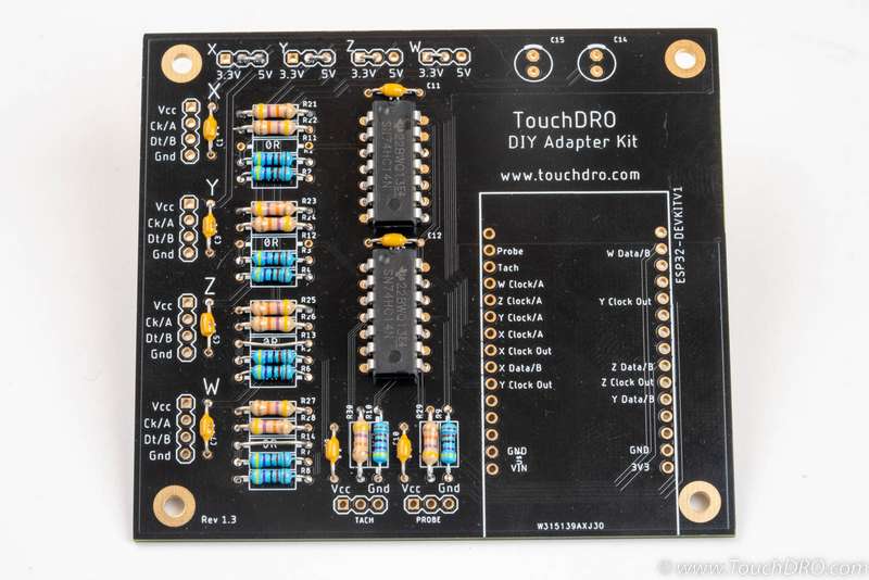
The 14-pin 74HC14 ICs go into positions IC1 and IC2 with the notch facing the top of the board (this is important!). The ICs come with leads pre-formed from the factory, but in most cases they need to be squeezed together gently to alight the pins with the holes. Once you insert them into their positions, the springiness of the pins will hole the ICs in place. Flip the board over and solder the pins.
Step 6 - Pin Headers (Optional)
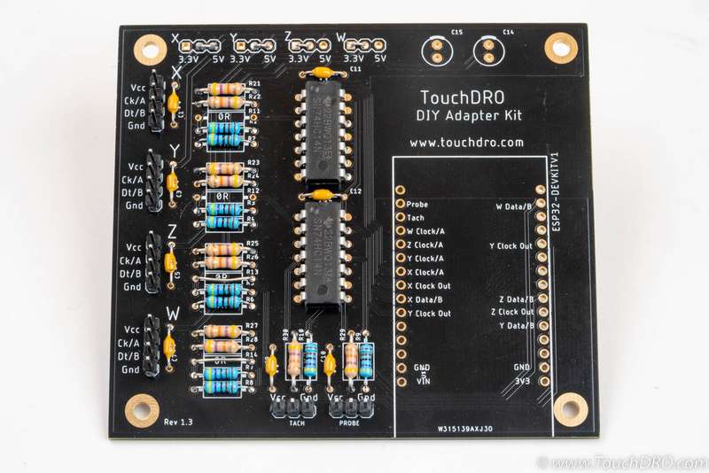
If you ordered the kit with pin headers (or have purchased your own headers), cut them into four 4-pin chunks and two 3-pin chunks using wire cutters.
Soldering these headers straight is a bit finicky. The easiest way is to hold the header in place and tack one pin. With your finger away from the hot pin, straighten the header until you are satisfied with it and then solder the remaining pins.
Step 7 - Electrolytic Caps
The two electrolytic "barrel" capacitors go into C14 and C15 positions. These capacitors are directional and will violently explode if soldered backwards. The light strips (negative lead) should face to the outside of the board, as shown in the photo.
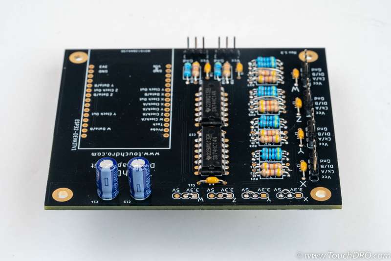
Step 8 - Test
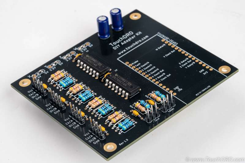
At this point you have completed the input conditioning circuit. Before soldering the ESP32 module, it's a good idea to check your connection and verify that the circuit works. For this you will need a multimeter and a few Dupont jumpers (provided in the "Adapter Board + DB9 Connectors" version of this kit.
Power Rails and Pull Up Resistors
To test the circuit we will use the ESP32 module to power it. If you have access to a bench power supply, you can use it instead.
- Using your multimeter in Continuity mode, check the
following:
- That there is no continuity between any Vcc, Data, and Clock pins and the ground (you can use one of the screw mounting holes for the ground lead.
- There should be continuity between the "VIN" pin and Probe Vcc, Tach Vcc, and any scale inputs configured for 5V
- There should be continuity between the "3V3" pin and Vcc pins for any scale inputs configured for 3.3V
- For any scale inputs configured for iGaging EZ-View DRO scales, there should be continuity between the relevant "Clock Out" pin and the "Ck/A" pin
- Connect the ESP32 module to the board using Dupond jumpers
- Locate the Vin (5V), 3.3V and Ground pins on the ESP32 module.
- Connect Vin to the Vcc pin of the tachometer input
- Connect Ground pin to the Gnd pin of the tachometer input
- If you have any inputs set for 3.3V, connect the 3V3 pin
- Power up the ESP32 module. Ensure that the Red LED is lit and Blue LED is blinking
- Using your multimeter in Voltage mode, check the following:
- Any scale inputs configured for 3.3V should show close 3.3V between Vcc and Gnd pins
- Any scale inputs configured for 5V should show close 5V between Vcc and Gnd pins
- Data and Clock pins for each scale should show voltage close to the selected supply voltage (Check between Ck/A and Dt/B, and the nearest Gnd)
- Probe and Tach inputs should show close to 5V between Vcc and Gnd
- Probe and Tach signal pins should show close to 5V between middle pin ang Gnd
Input Signal Wiring
While ESP32 is connected to the board and powered, we are going to check the function and wiring of the 74HC14 ICs. For this we will be checking voltage between the input pins on the ESP32 footprint.
- Check that
Cloc/A, Data/B pins for X,Y, Z, and W axis, as well as Probe and Tach pins on the ESP32 show 0V between the pin and the ground - For each axis Ck/A and Dt/B, and Probe/Tach signal pins:
- Short the input pin to the ground using a Dupont jumper wire
- Check the voltage on the ESP32 input pin. The voltage should be very close to 3.3V when the input pin is shorted
- Remove the shoring wire; ESP32 input should read 0V
If all of the above tests are successful, you have confirmed that the input circuit is functioning as expected. Otherwise recheck your solder joints around the problematic input and re-test again.
Step 9 - ESP32 Module
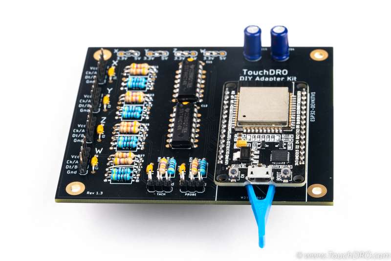
The ESP32 module should be mounted with the Micro-USB connector facing to the outside of the board. The fit might be pretty snug, and you might need to press the pins slightly inwards.
Step 10 - Scale Connection
This will depend on the type of the scales you are planning to use.
Glass/Magnetic Scales
Most glass and magnetic DRO scales on the market use Female D-Sub 9 ping (AKA DB9) connectors. If you ordered this kit with connectors, you received four female connectors and eight 20cm Dupont jumper wires. When cut in half, this will provide enough for 16 connections (4 per each scale).
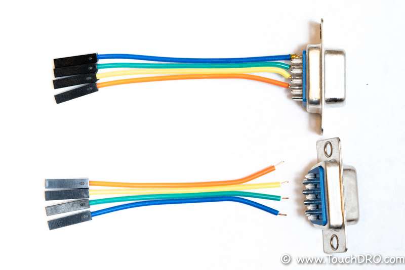
To connect the D-Sub connectors to the board, the kit includes a length of female-to-female ribbon cable. Start by cutting the cables in half. If necessary, you can trim the length first to accommodate your enclosure. Split the cut end into individual wires, strip about 2 mm of insulation off the end, and pre-tin the newly exposed wire. Solder the wires to the correct pins on the D-Sub connectors according to your scales pinout. The end result will look similar to the picture below.
To wire the connectors you will need to find the pinout of your particular scales. In most cases, the vendor from whom you purchased the scales should be able to provide the documentation. If the vendor is not able to provide the connector pinout, you can usually reverse engineer it following the instructions on the "How to Find Glass DRO Scale Pin Functions" page.
Capacitive Scales
Capacitive scales supported by this kit use either USB Mini-B or USB Micro-B connectors. The most common approach is to connect the scales using Mini-USB or Micro-USB breakout boards. Those can be readily obtained from many online retailers. The pinouts for those scales are listed on the pages linked from the "Supported Capacitive Scales" page.
Step 11 - Power Up
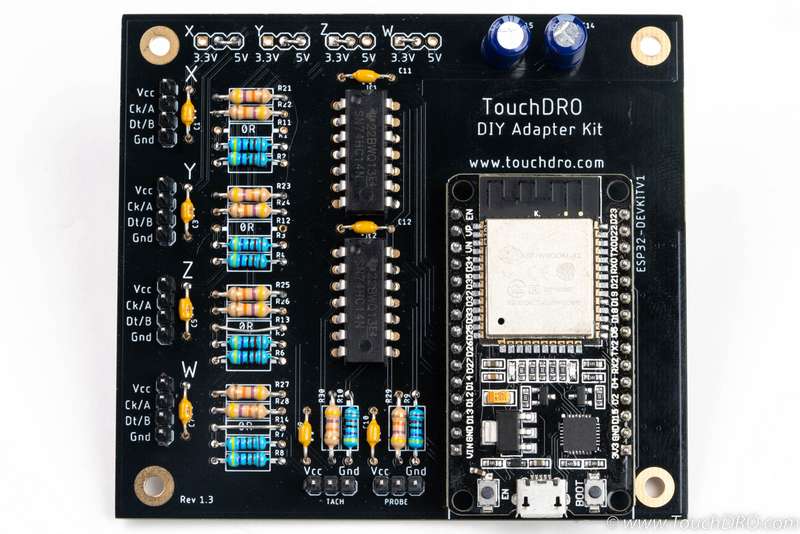
The finished adapter should look similar to the picture above. Before connecting the scales, it's a good idea to power it up and check if it's fully functional:
Immediately after power is connected, the red Power LED should light up and stay lit. The Heartbeat LED will blink about once per second.
If the power-up is successful, try pairing the Android device to the adapter and starting the TouchDRO application. The app should connect to the adapter and stay connected, even though it's not getting a position from the scales.
