Building DIY DRO Kit for iGaging/Shahe Scales
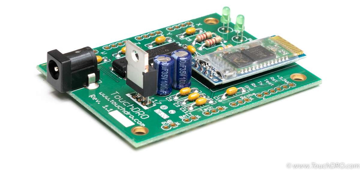
Building a TouchDRO DIY DRO Adapter Kit is very straightforward and doesn't require extensive soldering skills or deep knowledge of electronics. The kit has been designed to use relatively few components and laid out with ample space between leads in order to simplify the build process. If you don't have a lot of experience building electronic circuits, please read Tips For Building a Reliable DIY DRO Circuit first. The page covers the tools and materials needed to build the kit and provides a lot of useful information about soldering and electronic assembly.
Step 0 - Parts Inventory
Start by sorting and identifying all of the parts in the kit. The parts shown in the picture below are as follows:
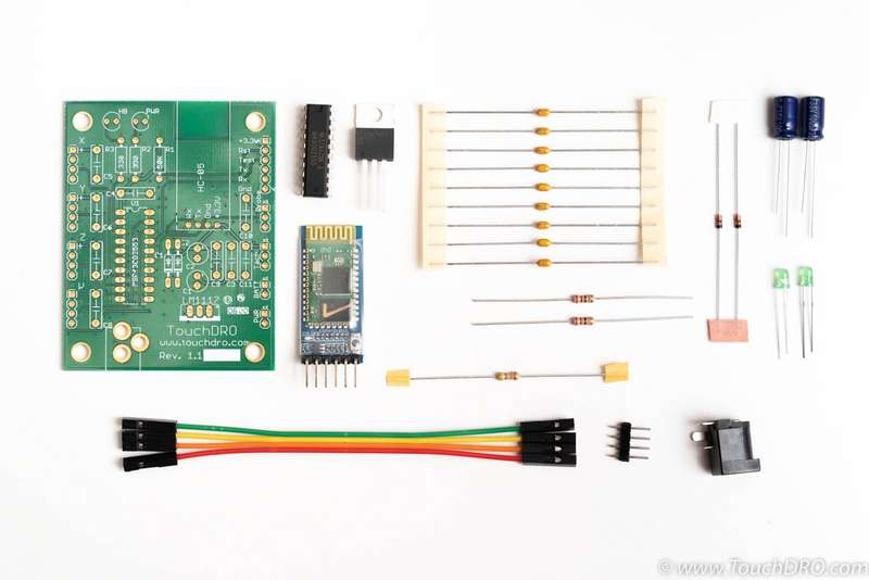
- TouchDRO Adapter PCB
- MSP430 microcontroller
- HC-05 Bluetooth module
- LM1113-3.3 voltage regulator
- 0.1uf ceramic capacitors (9 pcs)
- 47 KOhm resistor
- 330 Ohm resistors (2 pcs)
- Schottky diodes (2 pcs)
- 100uf Electrolytic capacitors (2 pcs)
- Green LEDs (2 pcs)
- Ribbon cable
- 4-pin header
- Power input jack
Step 1 - 0.1uF Bypass Capacitors
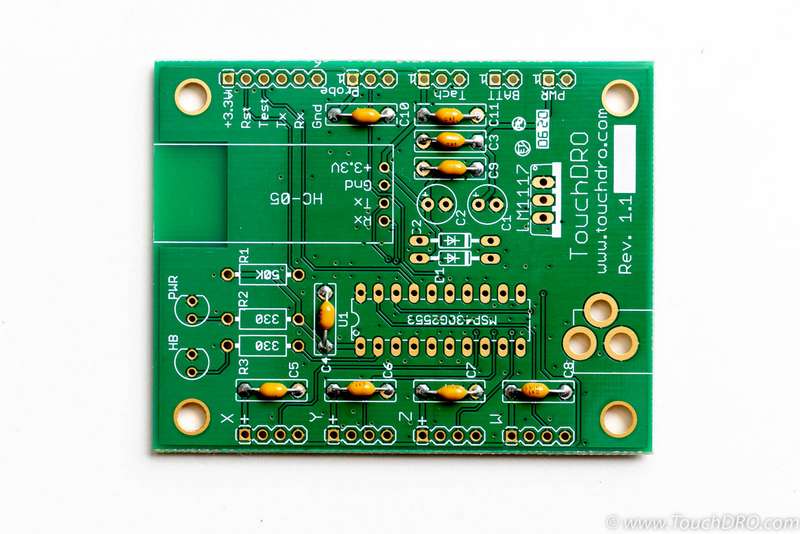
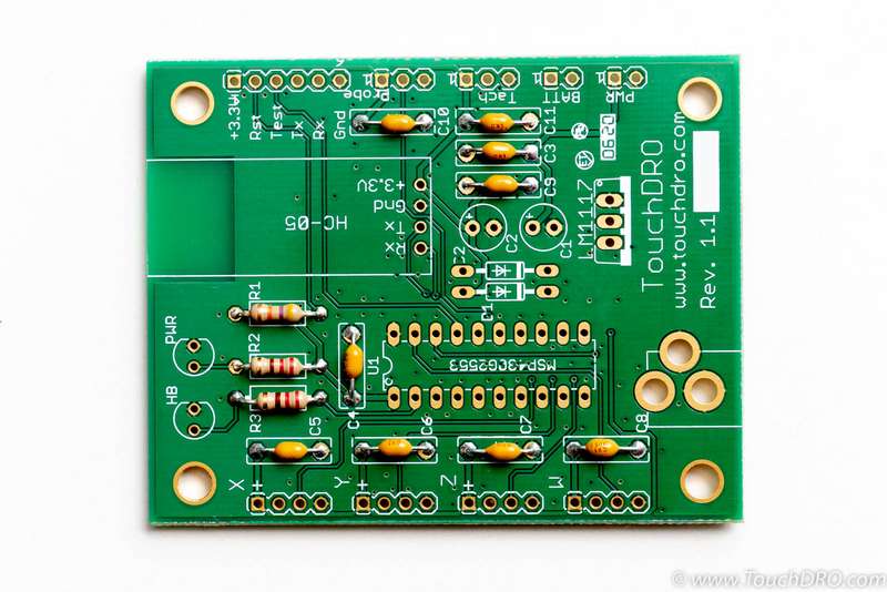
Cut nine of 0.1uF ceramic capacitors off the tape and form the leads using the included lead forming jig as shown in the picture.
Insert the capacitors into locations marked C3, C4, C5, C6, C7, C8, C9, C10, and C11 on the PCB. After inserting each cap, bend the leads slightly outwards to stop it from falling out. Flip the board over and solder the pins. Once all capacitors are soldered, cut off the excess leads, leaving about 1mm above the solder fillet. Your board should look similar to the picture below.
Step 2 - 330 Ohm Resistors
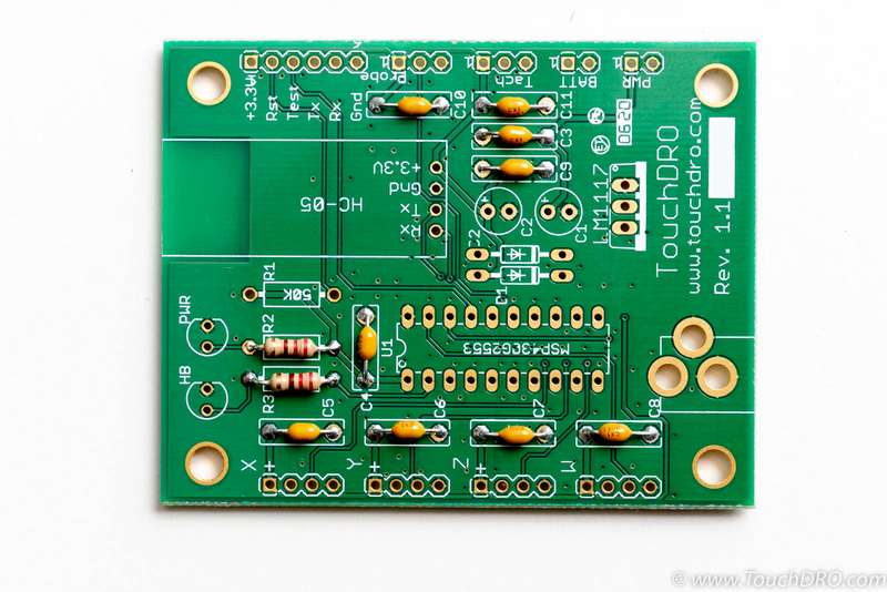
330 Ohm resistors have two orange bands followed by a brown band when looked with the gold band facing to the right; they need to be inserted into locations marked R2 and R3 (also marked 330). Form the leads and solder the parts similarly to step 1.
Step 3 - 47 KOhm Resistor
The remaining resistor will have yellow, purple and orange bands and should go into location marked R1 (also marked 50K) following the same process as the previous two steps.
Step 4 - Schottky Diodes
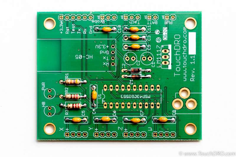
Cut the diodes off the tap and form the leads using the second position on the included lead forming jig. The diodes can be configured two different ways, depending on whether or not you want to power the scales from a separate battery pack:
Separate Power to Scales
If you intend to power the scales from an external battery pack, rather than from the PCBs 3.3V rail, only D2 should be populated and D1 should be skipped. This will disconnect the scales' power supply pins from the on-board voltage regulator.
Standard Configuration
Standard configuration is to power the scales from the PCBs 3.3V rail and optionally use a battery pack for backup power. In this case you will need to use both diodes.
Insert the diodes into locations marked D1 and D2 making sure that the black band on the diode body matches the white band on the PCB. Please note, their bodies are made of glass and are sensitive to overheating, so try to not overheat them during soldering.
Step 5 - MSP430 Microcontroller
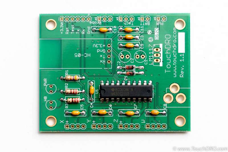
The microcontroller goes into the location marked U1 or MSP430G2553. The IC is directional and needs to be inserted with the notch on the body facing the same way as the notch on the silkscreen; the text will be flipped by 180 degrees compared to the silkscreen.
When inserting the part, it might be necessary to slightly bend the leads inward. This can be done by gently squeezing them between your fingers or against a flat surface by a small amount.
Step 6 - LEDs
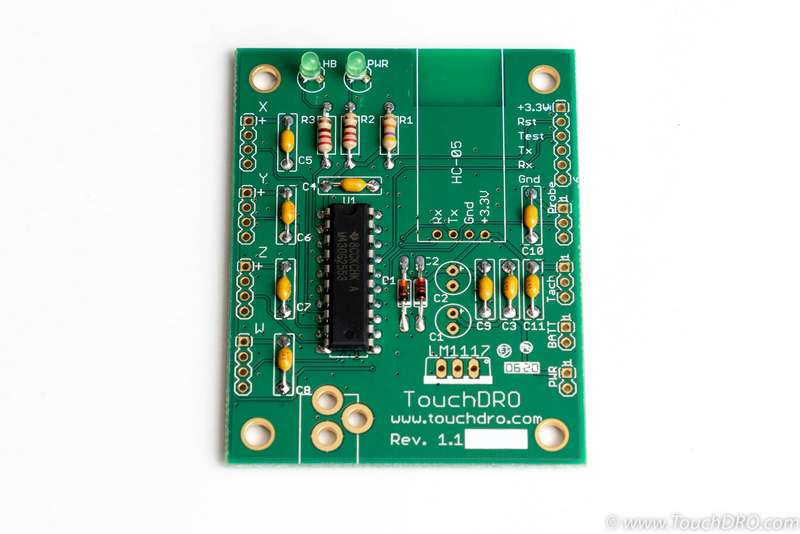
The LEDs should be inserted into locations marked "HB'' and "PWR" (short for HeartBeat and Power). The parts are directional, so they need to be inserted so the flat tab on the LED faces the same way as the tab on the PCB silkscreen. They can be mounted flush with the board but it's best to leave a bit of space for the solder filet. Alternatively, you might want the LED domes to protrude from the case for better visibility, in which case you'll need to solder them at an appropriate height.
Step 7 - Power Input Jack
The holes for the power are intentionally left slightly oversized to allow for some adjustment. Start by soldering one lead. Straighten the part as needed and solder the remaining two leads.
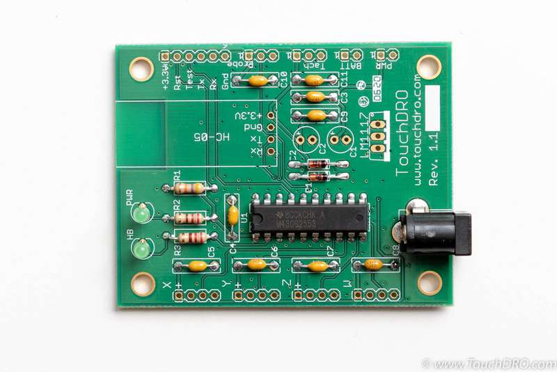
Step 8 - Electrolytic Capacitors
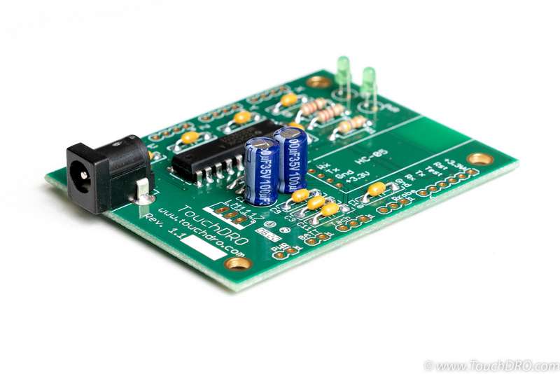
Electrolytic capacitors should be inserted into locations marked C1 and C2. The part is polarized and should be mounted so the vertical bands point towards the voltage regulator, as shown in the picture below.
Step 9 - Voltage Regulator
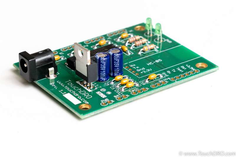
The voltage regulator goes into location marked LM1117. Insert the voltage regulator into the PCB with the metal tab facing the same way as the thick white band on the silkscreen. Flip the board and solder one pin while holding the part as straight as possible. Tweak/straighten the part as needed and solder the remaining two pins.
Step 10 - Bluetooth Module
There are three options for the Bluetooth module installation depending on the type of the enclosure you intend to use.
Using Ribbon Cable
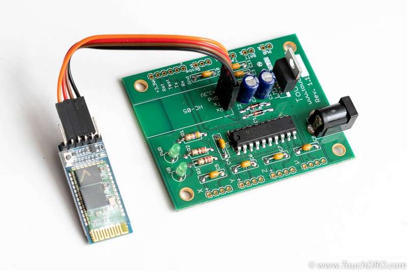
Solder the 4-pin header into the HC-05 location and using the included ribbon cable connects the module to the TouchDRO adapter. Please note, in this case Rx on the module should go to Rx on the PCB, Tx to Tx, Gnd to Gnd and +3.3V to +3.3V.
Standing Up
Using your clippers or side cutters, cut off one pin from each side of the Bluetooth module, so only the middle four pins are left. Insert the module into the PCB such that pin functions match up (the component side of the module should face towards the electrolytic capacitors.
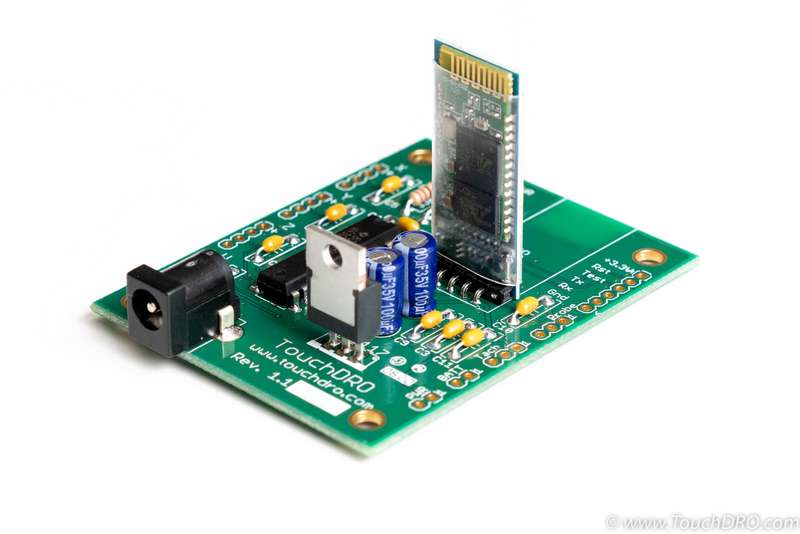
Laying Flat
In order to lay the module flat on the PCB, the 6-pin right-angle header needs to be desoldered and the 4-pin straight header soldered to the underside of the module. The easiest way to desolder the header is to cut off the pins right above the black plastic piece, remove the plastic piece and desolder each pin individually. After the pins are desoldered, you will need to remove excess solder from the holes using some solder wick. Once the holes are cleaned, insert the 4-pin header from the reverse side of the module as shown below and solder the pins. Solder the module to the TouchDRO PCB and clip the excess leads.
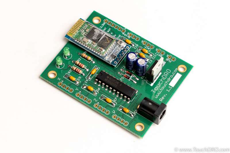
Step 11 - Power Up
Before connecting the scales, it's a good idea to power it up and check if it's fully functional:
Immediately after power is connected, the Power LED should light up and stay lit. The Heartbeat LED will blink rapidly for 2 seconds and then start blinking about once per second. Blue LED on the Bluetooth module should be blinking, indicating that the module is ready to pair.
If the power-up is successful, try pairing the Android device to the adapter and starting the TouchDRO application. The app should connect to the adapter and stay connected, even though it's not getting a position from the scales.
Step 12 - Connect the Scales
There are two approaches to connecting the scales to your DRO adapter. The most straightforward is to use a set of USB breakout boards with connectors appropriate for your scale cables. The boards usually have the pins labeled, so making correct connections is very easy. Alternatively, you can cut off the USB connector on the end of the cable that is plugged into the display and solder the wires directly into the board. In this case, you will need to use a multimeter to identify what each wire does; keep in mind that going by the color code is unreliable.
The information about the scale's USB connector pin mapping or the information on how to identify the pin functions can be found by following the appropriate link from the Supported Capacitive Scales page.
