Building DIY DRO Kit for Glass Scales
The TouchDRO DIY Kit for Glass Scales is designed to be flexible, yet easy to build. The assembly process requires only a few basic soldering tools and supplies and should take around an hour.
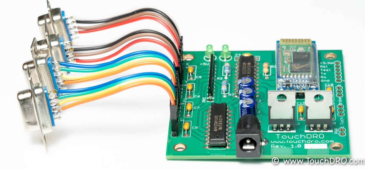
The success of the DIY Adapter Kit build and it's long-term reliability depend on the quality of the work you are able to do while assembling it. When the adapter you just built fails to work correctly or fails prematurely, the troubleshooting process can be time-consuming and frustrating. Fortunately, it's very easy to avoid those problems by following the instructions while prepping the parts and soldering. In order to avoid potential mistakes, please review the "Tips For Building a Reliable DIY DRO Circuit"
Additionally, please keep in mind that several components used by this adapter are directional, and a few look very similar.
Finally, if you are not proficient with soldering or don't have the right tools and materials, please consider buying a pre-made adapter. While it's more expensive up front, you will save yourself much frustration and will end up with a more reliable digital readout at the end.
Step 0 - Parts Inventory
Start by sorting and identifying all of the parts in the kit. The parts shown in the picture below are as follows:
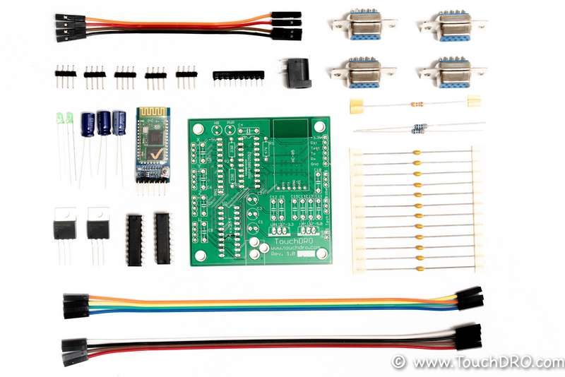
- TouchDRO Adapter PCB
- MSP430G2553 Microcontroller
- HC-05 BlueTooth Transceiver module
- SN…. Input Buffer
- LM1117-3.3 Voltage Regulator, 3.3V
- LM1117-5 Voltage Regulator, 5V
- 49Kohm Resistor Network
- 47 KOhm Resistor
- 330 Ohm Resistor (2 Pcs.)
- 0.1 uF Ceramic Capacitor (12 Pcs.)
- 100 uF Electrolytic Capacitor (3 Pcs.)
- Blue Led, 3mm (2 Pcs.)
- D-Sub 9 Connector, Female (4 Pcs.)
- Dupont Jumper Wire (20 Pcs.)
- Pin Header, 0.1" Inch (20 Pins)
- Power Input Jack
Step 1 - 0.1uF Ceramic Capacitors
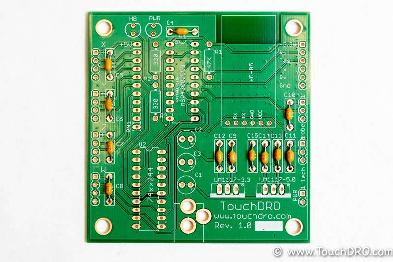
Cut the 0.1uF ceramic capacitors off the tape and form the leads using the included lead forming jig. They use 0.3" spacing, so use the notch that is closed to the narrow end.
Insert the capacitors into locations marked C4-C15 on the PCB as shown in the picture above. After inserting each cap, bend the leads slightly outwards to stop it from falling out. Flip the board over and solder the pins. Once all capacitors are soldered, cut off the excess leads, leaving about 1mm above the solder fillet. Your board should look similar to the picture below.
Step 2 - Axial Resistors
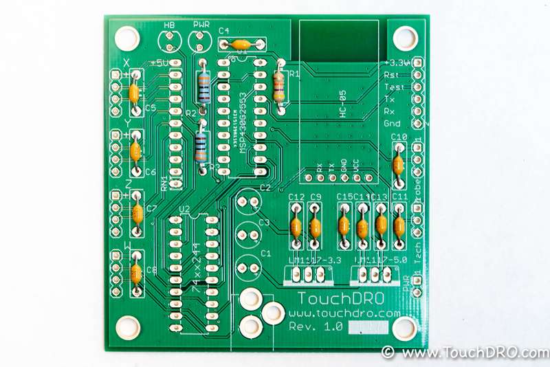
The kit comes with two types of resistors. The two blue resistors are low-value current limiting resistors for the LEDs that need to be installed into locations R2 and R3. The third, 47Kohm resistor is used to pull the reset pin of the MSP430 to 3.3V. It needs to be installed into the R1 position. Resistors use 0.4" lead spacing, so they need to be formed using the second notch on the lead forming jig. The end result should look like the picture below
Step 3 - MSP430 and Buffer IC
The adapter uses two different 20-pin ICs - the MSP430 microcontroller and the 74HC244 buffer. Physically, they look very similar; so, to identify them, you might need to look at the marking on the top of the IC case.
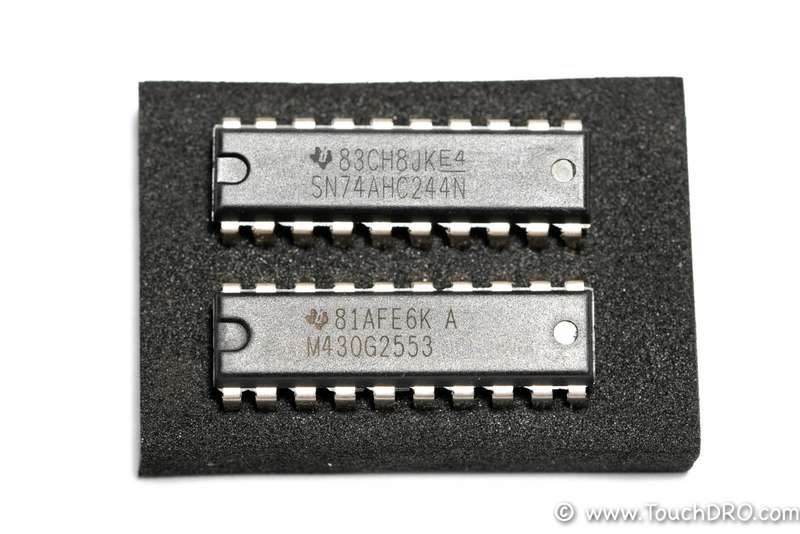
MSP430 needs to be installed into the U1 position and the buffer goes into the U2 position. Please note, the ICs are directional, so make sure that the notch on the IC matches the marking on the PCB. Furthermore, from the factory, the leads are slightly bent out and the IC will not fit into the board. To fix this, gently squeeze the leads together between your fingers to bend them inwards.
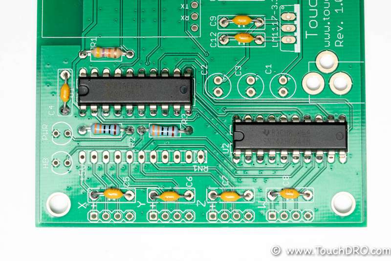
Step 4 - Resistor Network
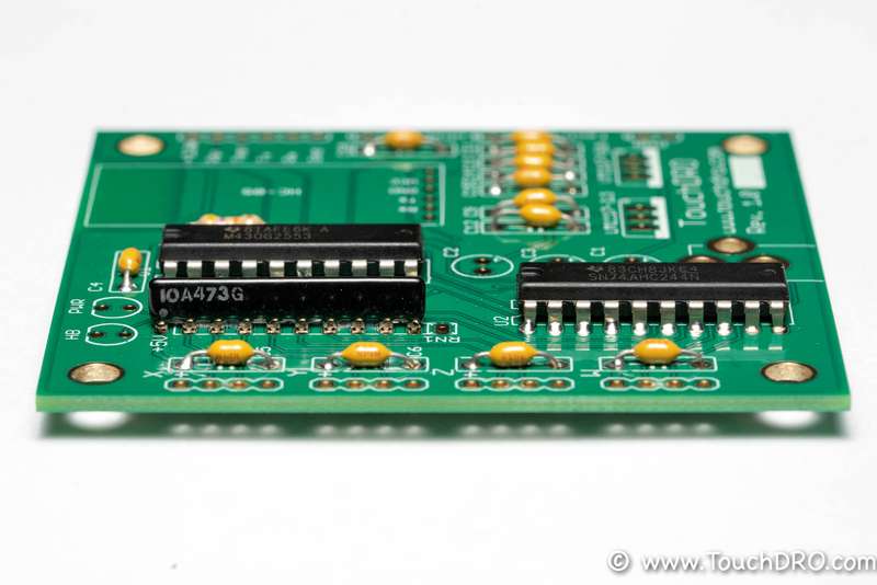
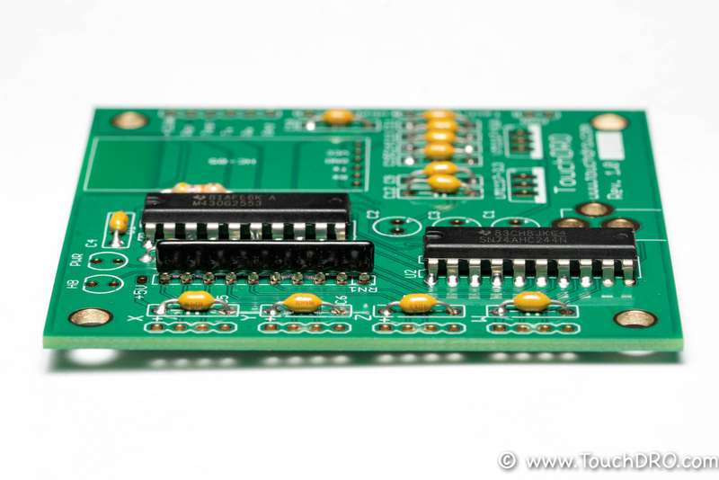
The resistor network is the black 10-pin component. It is used to pull the scale inputs up to 5V or down to the ground. The configuration depends on the type of your scales. Most Chinese glass scales work best with the resistors installed in pull-down configurations as do the majority of the Chinese magnetic scales. Other scales might have different requirements; therefore, you will need to refer to the scales' manual for more information. Finally, open-collector optical encoders require the resistors to be installed in a pull-up configuration.
To accommodate both configurations, the RN1 position has one extra hole. To set the inputs for pull-up configuration, install the resistor network with the first pin (marked with a white dot) into the hole that is closest to the left edge of the board (marked +5V), as shown in the picture below. Note that the writing is facing towards you.
To set the inputs for pull-down mode, insert the first pin into the hole closest to the right edge of the board, marked with a square. Please note that the writing is facing away from you, towards the IC in this case.
Step 5 - LEDs
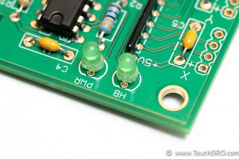
This adapter uses two green LEDs, one that is lit when the board is receiving power, and the other blinks once-per-second when the microcontroller is running. The locations are marked "PWR" for the power LED and "HB" for the heartbeat LED.
Please note, the LEDs are directional - there is a tab on one side of the body that needs to match the marking on the PCB. The correct installation is shown in the picture below.
Step 6 - Power Input Jack
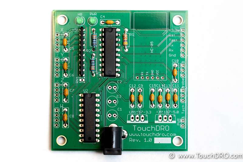
The power input jack has three pins and can be inserted in only one direction. The holes are intentionally made loose to accommodate some lateral adjustment. Insert the power hack into its position, lay the board with the jack facing down, and solder one of the pins. Once the solder solidifies, check the part for alignment, tweak it as needed, and solder another pin while holding the power jack in place. If the part still looks straight, solder the last remaining pin.
Step 7 - Electrolytic Capacitors
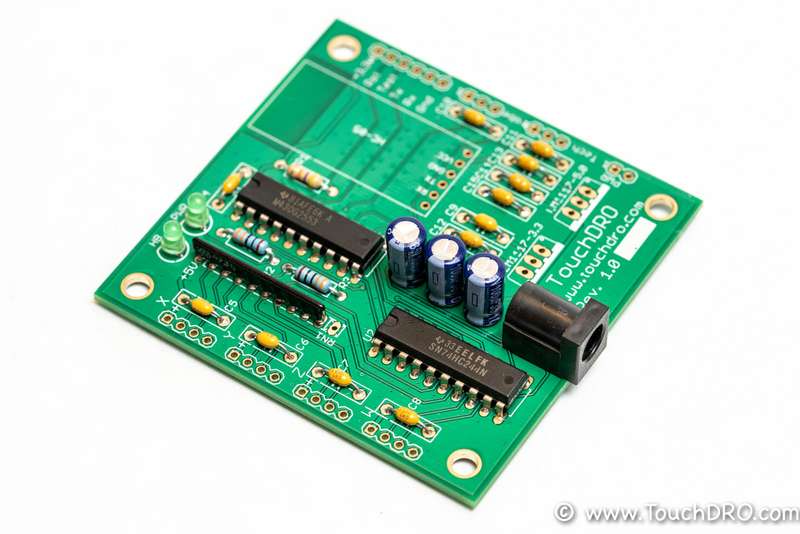
The three blue electrolytic capacitors should be installed into C1, C2, and C3 positions. These capacitors are directional and will explode if installed incorrectly. The positive pin on the board is marked with a "+"; the gray vertical stripe marks the negative pin of the capacitors. The end result should look similar to the picture below.
Step 10 - Voltage Regulators
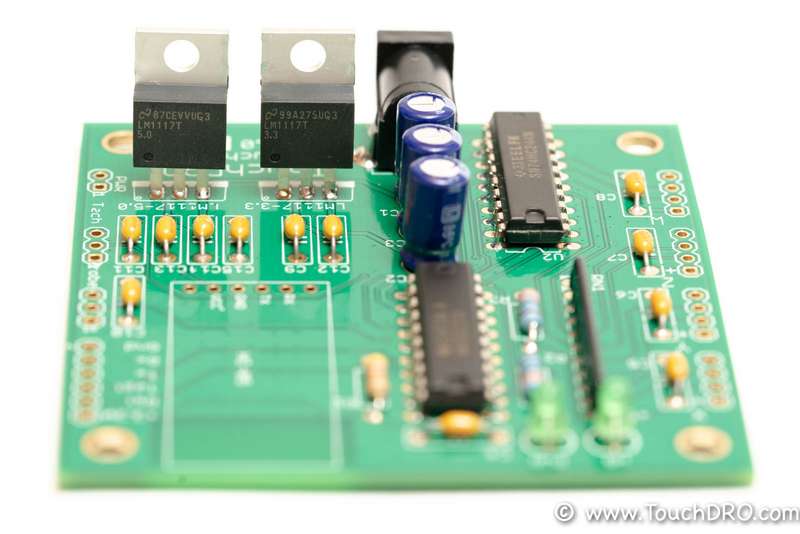
This version of the adapter uses two voltage regulators to provide clean supply voltage to the MSP430 microcontroller and the DRO scales. The part looks almost identical with the exception of the "5.0" or "3.3" marking on their bodies; there are corresponding markings on the PCB that indicate where each regulator should be installed. Furthermore, the regulators are directional and need to be installed with the tabs facing the "TouchDRO" writing. Finally, ensure that the tabs are not contacting each other and are not touching any metal. They are connected to the regulators' output, and connecting 5V to 3.3V rail will damage the microcontroller and the voltage regulator.
Step 11 - Bluetooth Module
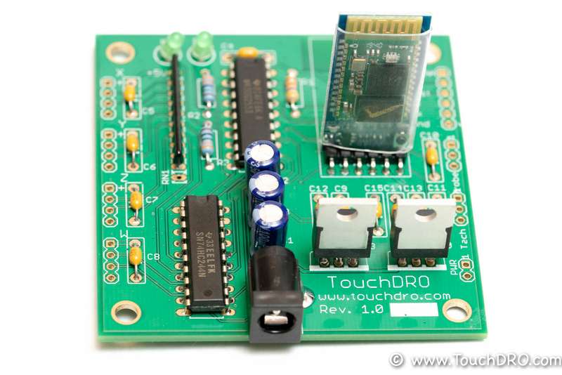
There are three different ways to mount the HC-05 BlueTooth transceiver module.
The simplest is to mount it standing up, as shown in the picture below. This configuration has the obvious downside of increasing the vertical height of the adapter, but since the BlueTooth antenna is farther away from the PCBs ground plane and other components, the reception will be slightly better.
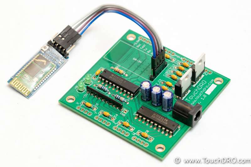
The second way is to use the provided 4-pin ribbon cable and mount the HC-05 away from the board. For this, you will need to solder one of the included 4-pin headers into the middle four holes (marked Rx, Tx, GND, and VCC).
Finally, the PCB provides enough space to mount the module laying flat. Unfortunately, this configuration will require desoldering the 6-pin right-angle header from the module. Once the header is removed and solder is cleared from the holes, install one of the 4-pin headers into the four middle holes on the PCB and solder the module as shown in the picture below. There will be a small gap between the board and the module, which is desirable for better reception.
Step 12 - Scale Connections
The vast majority of glass DRO scales use 9-pin male D-Sub connectors; therefore, the kit ships with four matching female connectors. Since there is no standard connection scheme, you will need to find the pinout for your scales. This can be found in the datasheet if one was provided with the scales. Otherwise, please refer to the "How to Find Glass DRO Scale Pin Functions".
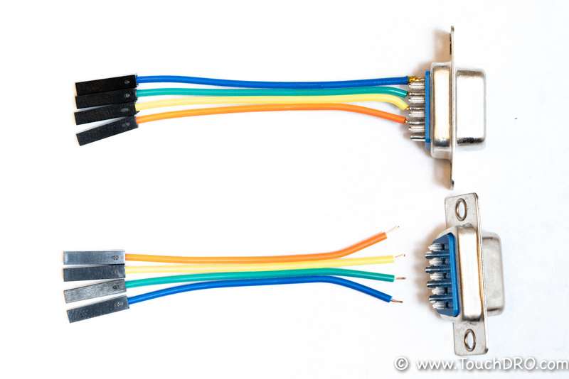
To connect the D-Sub connectors to the board, the kit includes a length of female-to-female ribbon cable. Start by cutting the cables in half. If necessary, you can trim the length first to accommodate your enclosure. Split the cut end into individual wires, strip about 2mm of insulation off the end, and pre-tin the newly exposed wire. Solder the wires to the correct pins on the D-Sub connectors according to your scales pinout. The end result will look similar to the picture below.
Step 13 - Power Up
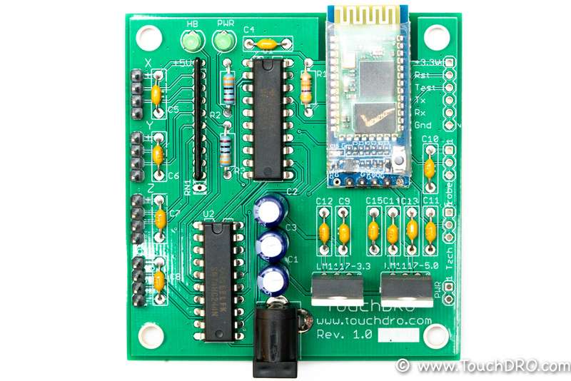
The finished adapter should look similar to the picture above. Before connecting the scales, it's a good idea to power it up and check if it's fully functional:
Immediately after power is connected, the Power LED should light up and stay lit. The Heartbeat LED will blink about once per second. Small red LED on the Bluetooth module should be blinking, indicating that the module is ready to pair.
If the power-up is successful, try pairing the Android device to the adapter and starting the TouchDRO application. The app should connect to the adapter and stay connected, even though it's not getting a position from the scales.
